Seagate ST15150N Product Manual - Page 62
Enable ST15150W Drive Terminator. Jumper installed - jumper settings
 |
View all Seagate ST15150N manuals
Add to My Manuals
Save this manual to your list of manuals |
Page 62 highlights
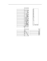
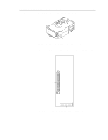
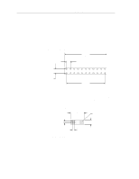
52 ST15150N/ND/W/WD/WC/DC Product Manual, Rev. D Block Pins Function J01 1 & 2* Terminator power supplied from the drive. 2 & 4* Terminator power supplied from the SCSI bus. 1 & 3 Terminator power supplied to the SCSI bus. 1 & 3 and Terminator power supplied to the SCSI bus and drive. 2 & 4* - Host adapter or other device on the SCSI bus provides terminator power to the external terminator (no jumper on any of the J01 pins). J4 1 & 2 Write Protect option. Jumper installed write protects the entire disc drive. Default is no jumper. 3 & 4 Delay Motor Start option. Jumper installed waits for 10 seconds for each target ID number plus a maximum power-up delay of 3 seconds before starting the spindle motor automatically. Default is no jumper. Example: If target ID is equal to three (3) (3 × 10) + 3 = 33 Target spindle motor starts in 33 seconds. 5 & 6 Enable Motor Start option. Jumper installed causes the target to wait for the Start Unit command from the SCSI host. No jumper installed causes the unit to look at the Delay Motor Start jumper. Default is no jumper. 7 & 8 Parity Disable option. Jumper installed causes parity checking and error reporting to be disabled. Default is no jumper. 9 & 10 Reserved. Default is no jumper. 11 & 12* Enable ST15150W Drive Terminator. Jumper installed enables the drive terminator on ST15150W drives. Jumper removed disables the drive terminator. Default is no jumper. 13 &14 Reserved. Default is no jumper. J5 1 &2** SCSI ID selector 0 3 &4** SCSI ID selector 1 5 &6** SCSI ID selector 2 7 &8** SCSI ID selector 3 9 & 10 Remote LED connector. Pin 9 is cathode (neg). Pin 10 is anode (pos). Pin 10 is current limited through a 1K ohm, 1/10W resistor. 11 &12 Spindle sync cable connector. Pin 11 is the SSREF+ or reference index signal. Pin 12 is Ground. * Valid for single-ended (ST15150W) drives only. ** See Figure 22 to set the SCSI ID.
-
 1
1 -
2
-
3
-
4
-
5
-
6
-
7
-
8
-
9
-
10
-
11
-
12
-
13
-
14
-
15
-
16
-
17
-
18
-
19
-
20
-
21
-
22
-
23
-
24
-
25
-
26
-
27
-
28
-
29
-
30
-
31
-
32
-
33
-
34
-
35
-
36
-
37
-
38
-
39
-
40
-
41
-
42
-
43
-
44
-
45
-
46
-
47
-
48
-
49
-
50
-
51
-
52
-
53
-
54
-
55
-
56
-
 57
57 -
 58
58 -
 59
59 -
 60
60 -
 61
61 -
 62
62 -
 63
63 -
 64
64 -
 65
65 -
 66
66 -
 67
67 -
68
-
69
-
70
-
71
-
72
-
73
-
74
-
75
-
76
-
77
-
78
-
79
-
80
-
81
-
82
-
83
-
84
-
85
-
86
-
87
-
88
-
89
-
90
-
91
-
92
-
93
-
94
-
95
-
96
-
97
-
98
-
99
-
100
-
101
-
102
 |
 |
