Sharp CD-ES9 Service Manual - Page 14
] CD - stereo system cd es900
 |
View all Sharp CD-ES9 manuals
Add to My Manuals
Save this manual to your list of manuals |
Page 14 highlights
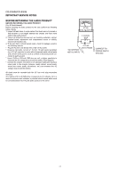
CD-ES900/CD-ES99 [3] CD section CD Error code description Error 01 10* 11* 20* 21* 31 Explanation When Pickup set inner position, inner switch cannot detect 'ON' level for 10 secs. CAM error. Can't detect CAM switch when CAM is moving. When it detect CAM operation error during initialize process. TRAY error. Can't detect TRAY switch when TRAY is moving. When it detect TRAY operation error during initialize process. When it change to CD function, DSP cannot read initial data. * 'CHECKING' If Error is detected, 'CHECKING' will be displayed instead of 'ER-CD**'. 'ER-CD**' display will only be displayed when error had been detected for the 5th times. Standard Specification of Stereo System Error Message Display Contents Error Contents CD Pickup Mechanism Error. CD Changer Mechanism Error. DISPLAY 'ER-CD01' 'ER-CD**' (*) Notes PU-IN SW Detection NG. 10: CAM SW Detection NG during normal operation. 11: CAM SW Detection NG during initialize process. 20: TRAY SW Detection NG during normal operation. 21: TRAY SW Detection NG during initialize process. TUNER CD DSP Communication Error. Focus Not Match/IL Time Over PLL Unlock 'ER-CD31' 'NO DISC' FM 87.5 MHz DSP COMMUNICATION ERROR PLL UNLOCK (*) CHECKING: If Error is detected, 'CHECKING' will be displayed instead of 'ER-CD**'. 'ER-CD**' display will only be displayed when error had been detected for the 5th times. Speaker abnormal detection and +B PROTECTION display. In case speaker abnormal detection or +B PROTECTION had occurred, it can be checked by pressing 'POWER', ' ' and 'X-BASS' button. Micro Computer version number will be displayed as "U******". Press 'VIDEO/AUX' button during version number display and then press 'POWER', 'MEMORY/SET' and 'VIDEO/AUX' button. Display will show "S**B**". S is referring to speaker abnormal detection and B is referring to +B PRPTECTION. ** is in hex values. +B PROTECTION is condition when irregular process occur on power supply line. BEFORE TRANSPORTING THE UNIT The following process need to be taken after set tapering/parts replacement. 1. Press the ON/STAND-BY button to enter stand-by mode. 2. While pressing down the button and the X-BASS/DEMO button, press the ON/STAD-BY button. The Micro Computer version number will be displayed as "U******". 3. Press OPEN/CLOSE button until "WAIT" o "FINISHED" appears. 4. Unplug the AC cord and the unit is ready for transporting. 2 - 2
-
 1
1 -
2
-
3
-
4
-
5
-
6
-
7
-
8
-
 9
9 -
 10
10 -
 11
11 -
 12
12 -
 13
13 -
 14
14 -
 15
15 -
 16
16 -
 17
17 -
 18
18 -
 19
19 -
20
-
21
-
22
-
23
-
24
-
25
-
26
-
27
-
28
-
29
-
30
-
31
-
32
-
33
-
34
-
35
-
36
-
37
-
38
-
39
-
40
-
41
-
42
-
43
-
44
-
45
-
46
-
47
-
48
-
49
-
50
-
51
-
52
-
53
-
54
-
55
-
56
-
57
-
58
-
59
-
60
-
61
-
62
-
63
-
64
-
65
-
66
-
67
-
68
-
69
-
70
-
71
-
72
-
73
-
74
-
75
-
76
-
77
-
78
-
79
-
80
-
81
-
82
-
83
-
84
-
85
-
86
-
87
-
88
-
89
-
90
-
91
-
92
-
93
-
94
-
95
-
96
-
97
-
98
-
99
-
100
 |
 |
