Sony DVPNS61 Service Manual
Sony DVPNS61 Manual
 |
View all Sony DVPNS61 manuals
Add to My Manuals
Save this manual to your list of manuals |
Sony DVPNS61 manual content summary:
- Sony DVPNS61 | Service Manual - Page 1
RMT-D175A/RMT-D175P/RMT-D175C SERVICE MANUAL Photo : DVP-NS36 RMT-D175P Notes: Australia/NZ model only AEP Model DVP-NS36/NS37 Russian Model UK Model DVP-NS36 Canadian Model US Model DVP-NS45P/NS55P Argentina Model Brazilian Model E Model DVP-NS63P PX Model DVP-NS55P Australia/New Zealand Model - Sony DVPNS61 | Service Manual - Page 2
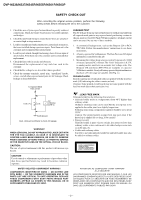
DVP-NS36/NS37/NS45P/NS55P/NS61P/NS63P SAFETY CHECK-OUT After correcting the original service problem, perform the following -540A. Follow the manufacturers' instructions to use these instruments. 2. A battery-operated AC milliammeter. The Data Precision 245 digital multimeter is suitable for this - Sony DVPNS61 | Service Manual - Page 3
DVP-NS37/NS45P/NS55P/NS61P/NS63P TABLE OF CONTENTS SERVICE NOTE 1. Disc Removal Procedure (at POWER OFF 5 1. GENERAL WARNING 1-1 Notes About the Discs 1-1 Precautions 1-1 About This Manual 1-1 This Player Can Play the Following Discs 1-1 Index to Parts and Controls 1-2 Guide Troubleshooting - Sony DVPNS61 | Service Manual - Page 4
Function 6-3 7. ELECTRICAL ADJUSTMENT 7-1. Power Supply Output Voltage Check 7-1 7-2. Adjustment of Video System (DVP-NS36:AEP,UK/NS37 7-2 7-3. Adjustment of Video System (Except DVP-NS35/NS36:AEP,UK/NS37 7-4 8. REPAIR PARTS LIST 8-1. Exploded Views 8-1 8-1-1. Main Section 8-1 8-1-2. Mechanism - Sony DVPNS61 | Service Manual - Page 5
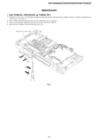
DVP-NS36/NS37/NS45P/NS55P/NS61P/NS63P SERVICE NOTE 1. DISC REMOVAL PROCEDURE (at POWER OFF) 1) Open dust cover to access to a hole insert a tapering driver into the aperture of the unit bottom, and - Sony DVPNS61 | Service Manual - Page 6
Additional Information 68 Troubleshooting 68 Self-diagnosis Function (When letters/numbers appear in the display). . . . . 71 Glossary 71 Specifications 73 Language Code List 74 Parental Control Area Code List 74 Index 75 About This Manual • Instructions in this manual describe the controls - Sony DVPNS61 | Service Manual - Page 7
DVP correctly finalized. For more information, refer to the operating instructions for the recording device. Note that some playback functions may sided disc product which mates DVD recorded material on one side with digital audio material on the other side. However, since the audio material - Sony DVPNS61 | Service Manual - Page 8
DVP-NS36/NS37/NS45P/NS55P/NS61P/NS63P Guide to the Control Menu Display Use the Control a digital camera. Hookups Hooking Up the Player Follow steps 1 to 6 to hook up and adjust the settings of the player. Notes • Plug cords securely to prevent unwanted noise. • Refer to the instructions supplied - Sony DVPNS61 | Service Manual - Page 9
DVP-NS36/NS37/NS45P/NS55P/NS61P/NS63P digital input to coaxial digital input AV amplifier (receiver) with a decoder B [Speakers] Rear (R) Front (R) Subwoofer : Signal flow * The yellow plug is used for video signals (page 15). z Hint For correct speaker location, see the operating instructions - Sony DVPNS61 | Service Manual - Page 10
DVP-NS36/ ? Select the type of jack you are using. YES LINE OUTPUT L/R (AUDIO) DIGITAL OUTPUT NO 9 Press X/x to select the type of jack (if any) you are played. For more information about finalizing, refer to the operating instructions supplied with the DVD recorder. Notes on playing DTS sound tracks - Sony DVPNS61 | Service Manual - Page 11
DVP-NS36/NS37/NS45P/NS55P/NS61P/NS63P Additional operations CLEAR REPLAY ADVANCE Note Depending on the VIDEO CD, "Press ENTER" in step 3 may appear as "Press SELECT" in the instructions supplied with the disc. In this case, press H. RETURN ENTER 1 Start playing a VIDEO CD with PBC functions - Sony DVPNS61 | Service Manual - Page 12
DVP-NS36/NS37/NS45P/NS55P/NS61P/NS63P Various Play Mode Functions (Programme Play, Shuffle Play, Repeat Play, A-B Repeat Play) 12(27) 18(34) T 1:32:55 OFF - Sony DVPNS61 | Service Manual - Page 13
DVP-NS36/NS37/NS45P/NS55P/NS61P/NS63P Searching for a Scene Searching for a Particular Point on a Disc (Search, Scan, Slow-motion Play, Freeze Frame) You can quickly - Sony DVPNS61 | Service Manual - Page 14
DVP DATA CD (DivX video files) recorded in multiple audio formats (PCM, Dolby Digital, MPEG audio, or DTS), you can change the audio format. If the audio signal formats. If "No audio data" appears, the player does not support the audio signal format contained in the disc. ◆ When playing a Super VCD - Sony DVPNS61 | Service Manual - Page 15
DVP-NS36 R: right) without using actual rear speakers. TVS was developed by Sony to produce surround sound for home use using just a stereo TV language. Depending on the DVD VIDEO, the choice of language varies. When 4 digits are displayed, they indicate a language code. See "Language Code List" on - Sony DVPNS61 | Service Manual - Page 16
DVP- , and DATA DVDs of Universal Disk Format (UDF). Refer to the instructions supplied with the disc drives and the recording software (not supplied) for file format. * "Design rule for Camera File system": Image standards for digital cameras regulated by JEITA (Japan Electronics and Information - Sony DVPNS61 | Service Manual - Page 17
DVP-NS36/NS37/NS45P/NS55P/NS61P/NS63P About playback order of albums, tracks, taken is displayed beside "DATE" in the Control Menu (page 11). Note that no date may appear depending on the digital camera. Note PICTURE NAVI does not work if "AUDIO (MP3)" is selected in "MODE (MP3, JPEG)" (page 51). - Sony DVPNS61 | Service Manual - Page 18
DVP-NS36/NS37/NS45P/NS55P/NS61P/NS63P Viewing a slide show with sound (MODE 9660 Level 1/ Level 2 or Joliet, and DATA DVDs of Universal Disk Format (UDF). Refer to the instructions supplied with the disc drives and the recording software (not supplied) for details on the recording format. About - Sony DVPNS61 | Service Manual - Page 19
DVP-NS36/NS37/NS45P/NS55P/NS61P/NS63P Selecting a DivX video file 1 After step asks you for your password, then press ENTER. The display will ask you to enter a new 4-digit password. Parental Control (limited playback) Playback of some DVD VIDEOs can be limited according to a predetermined - Sony DVPNS61 | Service Manual - Page 20
DVP-NS36/NS37/NS45P/NS55P/NS61P/NS63P Controlling Your TV with the Supplied Remote You can control the sound level, input source, and power switch of your Sony your TV. ◆For RMT-D175P remote commander only Manufacturer Sony Aiwa Grundig Hitachi JVC LG Loewe Panasonic Philips Samsung Sanyo Sharp - Sony DVPNS61 | Service Manual - Page 21
DVP-NS36/NS37/NS45P/NS55P/NS61P/NS63P Settings for the Display (SCREEN SETUP) channels priority when you play a DVD VIDEO on which multiple audio formats (PCM, MPEG audio, DTS, or Dolby Digital format) are recorded. OFF No priority given. AUTO Priority given. Notes • When you set the item to - Sony DVPNS61 | Service Manual - Page 22
If you experience any of the following difficulties while using the player, use this troubleshooting guide to help remedy the problem before requesting repairs. Should any problem persist, consult your nearest Sony dealer. Power The power is not turned on. , Check that the mains lead is - Sony DVPNS61 | Service Manual - Page 23
DVP-NS36/NS37/NS45P/NS55P/NS61P/NS63P Self-diagnosis Function (When letters/numbers appear in the display) When the self-diagnosis function is activated to prevent the player from malfunctioning, a five-character service number (e.g., C 13 50) with a combination of a letter and four digits Sony - Sony DVPNS61 | Service Manual - Page 24
DVP-NS36/NS37/NS45P/NS55P/NS61P/NS63P SECTION 2 DISASSEMBLY Note: Follow the disassembly procedure in the numerical order given. 2-1. UPPER CASE 4 Two Tapping Screws 3 Tray Cover 1 - Sony DVPNS61 | Service Manual - Page 25
DVP-NS36/NS37/NS45P/NS55P/NS61P/NS63P 2-3. LOADING ASSEMBLY 4 Three Screws +BV3 (3-CR) 5 Loading Assembly a 1 FMO-009 Flat Flexible Cable (CN101, 24P) 2 MD-111 Harness (CN201, 6P) 3 FMS-010 Flat Flexible Cable (CN202, 5P) a 2-2 - Sony DVPNS61 | Service Manual - Page 26
DVP-NS36/NS37/NS45P/NS55P/NS61P/NS63P 2-4. OPTICAL PICK-UP (DEVICE, OPTICAL KHM-313CAA/C2RP) Note: Solder shortland before remove the FMO-009 Flat Flaxible Cable - Sony DVPNS61 | Service Manual - Page 27
PANEL, MV BOARD and IF BOARD 2-5-1. REAR PANEL, MV-51 and IF-144/IF-145 BOARDS (DVP-NS45P/NS55P/NS61P/NS63P/NS36:RUS) Note: Caution Point on the PWB IF-144/IF-145 When Screws +BV3 (3-CR) 2 Rear Panel 9 3 FSW-001 Flat Flexible Cable (CN403, 7P) q; IF-144 Board EXCEPT DVP-NS63P 0 IF-145 Board - Sony DVPNS61 | Service Manual - Page 28
NS36/NS37/NS45P/NS55P/NS61P/NS63P 2-5-2. REAR PANEL, MV-50 and IF-144 BOARDS (DVP-NS36:AEP/NS37) 5 FMO-009 Flat Flexible Cable (CN101, 24P) a 8 PM-127 Harness (CN501, 10P) 6 Five Screws +BV3 (3-CR) 3 MD-111 Harness (CN201, 6P) 4 FMS- - Sony DVPNS61 | Service Manual - Page 29
DVP-NS36/NS37/NS45P/NS55P/NS61P/NS63P 2-7. INTERNAL VIEWS TOP VIEW Optical Pick-Up (Device, Optical KHM-313CAA/C2RP/ Service Assembly) MS-203 MOUNT BOTTOM VIEW 2-6 - Sony DVPNS61 | Service Manual - Page 30
NS37/NS45P/NS55P/NS61P/NS63P MV-50 Board (DVP-NS36/NS37) (CPU, Servo-DSP, AVDEC, DRIVE, VIDEO EURO, AUDIO, POWER) MV-51 Board (DVP-NS45P/55P/61P/63P) (CPU, Servo-DSP, AVDEC, DRIVE, VIDEO, AUDIO, POWER) SW-468 Board (EXCEPT DVP-NS63P) (SWITCH) SW-475 Board (DVP-NS63P ) (SWITCH) IF-144 Board (EXCEPT - Sony DVPNS61 | Service Manual - Page 31
VFD DRIVER CIRCUIT Vkk EVER 3.3V IC407 3.3V REGULATOR IC EVER +5V IC404 IF MICON IC408 RESET IC MV-50 BOARD (DVP-NS36/NS37 ) (SEE PAGE 3-5 to 3-14) MV-51 BOARD (DVP-NS45P/NS55P/NS61P/NS63P ) (SEE PAGE 3-5 to 3-14) • Abbreviation AEP : AEP Model RUS : Russian Model UK : UK Model CND : Canadian - Sony DVPNS61 | Service Manual - Page 32
IC102 FLASH ROM Q411 Coaxial IC406 Audio DAC IC404, 405 Optical Out CN101 VCC 11 OPTICAL DEVICE IF-144 BOARD (EXCEPT DVP-NS63P) (SEE PAGE 4-9 to 4-10) IF-145 BOARD (DVP-NS63P ) (SEE PAGE 4-13 to 4-14) CN106 15 13 11 12 CN404 3576 F1 ND401 F2 FLD Q401,402 T401 DC - Sony DVPNS61 | Service Manual - Page 33
XTALI RGBSEL EUROVY WIDE DISC/XEXT WIDE R/Cr/Pr B/Cb/Pb Y/G CVBS Y C IC101 CXD9849R MICROPROCESSOR AV DECODER SERVO DSP 102 SCL 103 SDA 228 229 DVP-NS36:AEP,UK/NS37 ONLY 136 179 209 224 IFBSY 105 IFSCK 99 IFSDO 98 XIFCS 100 IFSDI 101 XSYSRST 110 RESET IC IC 108 - Sony DVPNS61 | Service Manual - Page 34
DVP-NS36/NS37/NS45P/NS55P/NS61P/NS63P 3-4. RF/SERVO BLOCK DIAGRAM BASE UNIT SEE PAGE 4-16) FOCUS COIL TRACKING COIL DVD/CD LD MODULE DVD/CD PDIC MV-50 BOARD (DVP-NS36:AEP,UK/NS37) (SEE PAGE 4-19 to 4-22) MV-51 BOARD (EXCEPT DVP-NS36:AEP,UK/NS37) (SEE PAGE 4-31 to 4-34) SPSP+ SLSL+ LIMIT CN201 1 - Sony DVPNS61 | Service Manual - Page 35
-NS36/NS37/NS45P/NS55P/NS61P/NS63P MV-50 BOARD (DVP-NS36:AEP,UK/NS37) (SEE PAGE 4-23 to 4-24) SYSTEM CONTROL (SEE PAGE 3-5 to 3-6) V Y C R G B VMUTE EUROVY WIDE RGBSEL DISCEXT 20 IC305 2 C/BAR PB 15 IC304 - Sony DVPNS61 | Service Manual - Page 36
/NS37/NS45P/NS55P/NS61P/NS63P 3-6. VIDEO (2) BLOCK DIAGRAM MV-51 BOARD EXCEPT(DVP-NS36:AEP,UK/NS37) (SEE PAGE 4-35 to 4-36) SYSTEM CONTROL (SEE PAGE 3-5 to 3-6) XV_MUTE V Y C Y Cb Cr IC304 VIDEO BUFFER MUTE 32 3 VIDEO IN VIDEO - Sony DVPNS61 | Service Manual - Page 37
Q406, Q409, Q410 MUTE DRIVER R442 R443 3.5Vp-p 20.82usec 3.5Vp-p 3-13 DVP-NS36/NS37/NS45P/NS55P/NS61P/NS63P Q407 MUTE IC405 1 D IN DVP-NS61P/NS63P: AR, BR OPTICAL DIGITAL OUTPUT EXCEPT DVP-NS36:AEP,UK/NS37 J301 DVP-NS36:AEP,UK/NS37 J401 Q411 BUFFER COAXIAL L L LINE OUT Q408 MUTE - Sony DVPNS61 | Service Manual - Page 38
PCONT POWER-SWITCH CN404 3 5 7 16 14 11 12 9 4 8 13 6 2 CN403 7 5 6 4 3 SYSTEM CONTROL MV-50/MV-51 (SEE PAGE 3-5 to 3-6) SW-468 BOARD (EXCEPT DVP-NS63P) (SEE PAGE 4-41 to 4-42) OPEN/CLOSE CN001 1 3 2 4 S006 5 Z R031 R030 R029 PREV NEXT PLAY S001 N S002 . R028 S003 > STOP PROG S004 - Sony DVPNS61 | Service Manual - Page 39
3 3.3V_MNT 4 XIFCS XIFBUSY 13 (FIM-013) 5 XIFBUSY IF-144 BOARD SIO 12 SOO 11 1-831-525-11 6 SIO 7 SOO (EXCEPT DVP-NS63P) GND 10 8 GND E IF-145 BOARD SCO 9 9 SCO (DVP-NS63P ) V_MUTE 8 10 V_MUTE SW+3.3V 7 11 SW+3.3V PCONT 6 12 PCONT EVER+5V 5 13 EVER+5V A_MUTE 4 14 A_MUTE SW - Sony DVPNS61 | Service Manual - Page 40
and when playing CD reference disc. • Readings are taken with a digital multimeter (DC 10MΩ). • Voltage variations may be noted due to parts by reference number, please include the board name. 4-3. WAVEFORMS MV-50 BOARD (DVP-NS36/NS37) 1 IC101 6 (CD PB) 8 IC101 200 C/BAR PB 15 IC304 - Sony DVPNS61 | Service Manual - Page 41
MV-51 BOARD (DVP-NS45P/55P/61P/63P) 1 IC101 6 (CD PB) 7 IC101 202 13 IC406 4 (DVD) 19 IC304 ea C/BAR PB 200nsec 2 200 C/BAR PB 1Vp-p 24MHz 12 IC406 4 (CD) 3.3Vp-p H 18 IC304 wa 3.5Vp-p 1Vp-p 22.67usec H H 1.4Vp-p 1.4Vp-p 4-5 DVP-NS36/NS37/NS45P/NS55P/NS61P/NS63P WAVEFORM 4-6 MV-51 - Sony DVPNS61 | Service Manual - Page 42
55P/61P/63P) (CPU, Servo-DSP, AVDEC, DRIVE, VIDEO, AUDIO, POWER) SW-468 Board (EXCEPT DVP-NS63P) (SWITCH) SW-475 Board (DVP-NS63P ONLY) (SWITCH) IF-144 Board (EXCEPT DVP-NS63P) (INTERFACE) IF-145 Board (DVP-NS63P ONLY) (INTERFACE) IF-144 BOARD IC404 B-7 IC406 A-5 IC407 C-7 IC408 B-6 Q401 D-7 Q402 - Sony DVPNS61 | Service Manual - Page 43
Diagram • Refer to page 4-7 for printed wiring board of IF-144 board. 1 2 3 4 5 6 7 8 9 10 11 12 13 14 15 IF-144 BOARD A (EXCEPT DVP-NS63P) INTERFACE -REF.NO.:1000 SERIES- XX MARK:NO MOUNT NO MARK:PB MODE MARKED:MOUNT TABLE B C D E F G H I J 4-9 INTERFACE 4-10 IF-144 - Sony DVPNS61 | Service Manual - Page 44
63P) (CPU, Servo-DSP, AVDEC, DRIVE, VIDEO, AUDIO, POWER) SW-468 Board (EXCEPT DVP-NS63P) (SWITCH) SW-475 Board (DVP-NS63P ONLY) (SWITCH) IF-144 Board (EXCEPT DVP-NS63P) (INTERFACE) IF-145 Board (DVP-NS63P ONLY) (INTERFACE) IF-145 BOARD IC404 B-7 IC407 B-6 IC408 C-8 Q401 D-7 Q402 D-7 D402 C-7 D403 - Sony DVPNS61 | Service Manual - Page 45
Diagram • Refer to page 4-11 for printed wiring board of IF-145 board. 1 2 3 4 5 6 7 8 9 10 11 12 13 14 15 IF-145 BOARD A (DVP-NS63P ) INTERFACE -REF.NO.:1000 SERIES- XX MARK:NO MOUNT NO MARK:PB MODE MARKED:MOUNT TABLE B C D E F G TO CN002 H I J 4-13 INTERFACE 4-14 - Sony DVPNS61 | Service Manual - Page 46
are a few cases that the part printed on this diagram isn't mounted in this model. Power Board MV-50 Board (DVP-NS36/NS37) (CPU, Servo-DSP, AVDEC, DRIVE, VIDEO EURO, AUDIO, POWER) MV-51 Board (DVP-NS45P/55P/61P/63P) (CPU, Servo-DSP, AVDEC, DRIVE, VIDEO, AUDIO, POWER) SW-468 Board (EXCEPT - Sony DVPNS61 | Service Manual - Page 47
11 (11) 1 2 3 4 5 6 CPU, Servo-DSP, AVDEC, DRIVE, VIDEO EURO, AUDIO, POWER MV-50 • : Uses unleaded solder. MV-50 BOARD (DVP-NS36/NS37) SIDE B E DVP-NS36/NS37/NS45P/NS55P/NS61P/NS63P D C B A 1 2 3 MV-50 BOARD SIDE A IC101 D-4 IC102 C-6 IC103 D-6 IC104 E-5 IC108 B-6 IC110 B-3 IC201 - Sony DVPNS61 | Service Manual - Page 48
4-17 for printed wiring board of MV-50 board. • Refer to page 4-4 for waveform 1 2 3 4 5 6 7 8 9 10 11 12 13 14 15 MV-50 BOARD (1/5) A (DVP-NS36/NS37) CPU, Servo-DSP, AVDEC -REF.NO.:1000 SERIES- XX MARK:NO MOUNT NO MARK:REC/PB MODE B C D E F G H I J 4-19 CPU, Servo-DSP - Sony DVPNS61 | Service Manual - Page 49
4-17 for printed wiring board of MV-50 board. • Refer to page 4-4 for waveform 1 2 3 4 5 6 7 8 9 10 11 12 13 14 15 MV-50 BOARD (2/5) A (DVP-NS36/NS37) DRIVE -REF.NO.:1000 SERIES- XX MARK:NO MOUNT NO MARK:REC/PB MODE (P1) B C D E F G H I J DRIVE MV-50 (2/5) 4-21 4-22 - Sony DVPNS61 | Service Manual - Page 50
17 for printed wiring board of MV-50 board. • Refer to page 4-4 for waveform 1 2 3 4 5 6 7 8 9 10 11 12 13 14 15 MV-50 BOARD (3/5) A (DVP-NS36/NS37) VIDEO EURO -REF.NO.:1000 SERIES- XX MARK:NO MOUNT NO MARK:REC/PB MODE B C D IC303 E F G H I J 4-23 VIDEO EURO 4-24 MV-50 - Sony DVPNS61 | Service Manual - Page 51
4-17 for printed wiring board of MV-50 board. • Refer to page 4-4 for waveform 1 2 3 4 5 6 7 8 9 10 11 12 13 14 15 MV-50 BOARD (4/5) A (DVP-NS36/NS37) AUDIO -REF.NO.:1000 SERIES- XX MARK:NO MOUNT NO MARK:REC/PB MODE B C IC403 D E F G H I J AUDIO MV-50 (4/5) 4-25 4-26 - Sony DVPNS61 | Service Manual - Page 52
Schematic Diagram • Refer to page 4-17 for printed wiring board of MV-50 board. • Refer to page 4-4 for waveform 1 2 3 4 5 6 MV-50 BOARD (5/5) A (DVP-NS36/NS37) POWER -REF.NO.:1000 SERIES- XX MARK:NO MOUNT NO MARK:REC/PB MODE B C D IC501 E F G H I J 4-27 7 8 9 10 11 12 13 - Sony DVPNS61 | Service Manual - Page 53
are a few cases that the part printed on this diagram isn't mounted in this model. Power Board MV-50 Board (DVP-NS36/NS37) (CPU, Servo-DSP, AVDEC, DRIVE, VIDEO EURO, AUDIO, POWER) MV-51 Board (DVP-NS45P/55P/61P/63P) (CPU, Servo-DSP, AVDEC, DRIVE, VIDEO, AUDIO, POWER) SW-468 Board (EXCEPT - Sony DVPNS61 | Service Manual - Page 54
4-29 for printed wiring board of MV-51 board. • Refer to page 4-5 for waveform 1 2 3 4 5 6 7 8 9 10 11 12 13 14 15 MV-51 BOARD (1/5) A (DVP-NS45P/55P/61P/63P) CPU, Servo-DSP, AVDEC -REF.NO.:1000 SERIES- XX MARK:NO MOUNT NO MARK:REC/PB MODE B C D E F G H I J 4-31 CPU - Sony DVPNS61 | Service Manual - Page 55
29 for printed wiring board of MV-51 board. • Refer to page 4-5 for waveform 1 2 3 4 5 6 7 8 9 10 11 12 13 14 15 MV-51 BOARD (2/5) A (DVP-NS45P/55P/61P/63P) DRIVE -REF.NO.:1000 SERIES- XX MARK:NO MOUNT NO MARK:REC/PB MODE (P1) B C D E F G H I J DRIVE MV-51 (2/5) 4-33 - Sony DVPNS61 | Service Manual - Page 56
29 for printed wiring board of MV-51 board. • Refer to page 4-5 for waveform 1 2 3 4 5 6 7 8 9 10 11 12 13 14 15 MV-51 BOARD (3/5) A (DVP-NS45P/55P/61P/63P) VIDEO -REF.NO.:1000 SERIES- XX MARK:NO MOUNT NO MARK:REC/PB MODE B C D E F G H I J 4-35 VIDEO 4-36 MV-51 (3/5) - Sony DVPNS61 | Service Manual - Page 57
29 for printed wiring board of MV-51 board. • Refer to page 4-5 for waveform 1 2 3 4 5 6 7 8 9 10 11 12 13 14 15 MV-51 BOARD (4/5) A (DVP-NS45P/55P/61P/63P) AUDIO -REF.NO.:1000 SERIES- XX MARK:NO MOUNT NO MARK:REC/PB MODE B C D E F G H I J AUDIO MV-51 (4/5) 4-37 4-38 - Sony DVPNS61 | Service Manual - Page 58
4-29 for printed wiring board of MV-51 board. • Refer to page 4-5 for waveform 1 2 3 4 5 6 7 8 9 10 11 12 13 14 15 MV-51 BOARD (5/5) A (DVP-NS45P/55P/61P/63P) -REF.NO.:1000 SERIESXX MARK:NO MOUNT NO MARK:REC/PB MODE B C XX D E F G H I J 4-39 4-40 The components identified by - Sony DVPNS61 | Service Manual - Page 59
-101- 11 (11) 3 • : Uses unleaded solder. For Schematic Diagram • Refer to page 4-41 for printed wiring board of SW-468 board. 1 2 3 4 5 6 7 SW-468 BOARD A (EXCEPT DVP-NS63P) SWITCH -REF.NO.:1000 SERIES- XX MARK:NO MOUNT NO MARK:REC/PB MODE B C D SWITCH SW-468 4-41 - Sony DVPNS61 | Service Manual - Page 60
A 1-868-235- 11 (11) 1 2 3 For Schematic Diagram • Refer to page 4-43 for printed wiring board of SW-475 board. 1 2 3 4 5 6 7 SW-475 BOARD A (DVP-NS63P) SWITCH -REF.NO.:1000 SERIES- XX MARK:NO MOUNT NO MARK:REC/PB MODE B C D E F SWITCH SW-475 4-43 For printed wiring board - Sony DVPNS61 | Service Manual - Page 61
/63P) (CPU, Servo-DSP, AVDEC, DRIVE, VIDEO, AUDIO, POWER) SW-468 Board (EXCEPT DVP-NS63P) (SWITCH) SW-475 Board (DVP-NS63P ONLY) (SWITCH) IF-144 Board (EXCEPT DVP-NS63P) (INTERFACE) IF-145 Board (DVP-NS63P ONLY) (INTERFACE) POWER BOARD (SRV1872WW) SIDE A IC101 A-4 Q211 A-6 D105 C-4 D106 B-4 D107 - Sony DVPNS61 | Service Manual - Page 62
Diagram • Refer to page 4-45 for printed wiring board of Power board. 1 2 3 4 5 6 7 8 9 10 11 12 13 14 15 POWER BOARD A POWER SUPPLY (SRV1872WW) (DVP-NS36/NS37/NS55P:PX/NS61P/NS63P) -REF.NO.:1000 SERIESXX MARK:NO MOUNT NO MARK:PB MODE MARKED:MOUNT TABLE B C D E 10 EVER-10V - Sony DVPNS61 | Service Manual - Page 63
/63P) (CPU, Servo-DSP, AVDEC, DRIVE, VIDEO, AUDIO, POWER) SW-468 Board (EXCEPT DVP-NS63P) (SWITCH) SW-475 Board (DVP-NS63P ONLY) (SWITCH) IF-144 Board (EXCEPT DVP-NS63P) (INTERFACE) IF-145 Board (DVP-NS63P ONLY) (INTERFACE) POWER BOARD (SRV1873UC) SIDE A IC101 A-4 Q211 A-6 D106 B-4 D107 A-3 D108 - Sony DVPNS61 | Service Manual - Page 64
Diagram • Refer to page 4-49 for printed wiring board of Power board. 1 2 3 4 5 6 7 8 9 10 11 12 13 14 15 POWER BOARD A POWER SUPPLY (SRV1873UC) (DVP-NS45P/NS55P: EXCEPT PX) -REF.NO.:1000 SERIESXX MARK:NO MOUNT NO MARK:PB MODE MARKED:MOUNT TABLE B C D E 10 EVER-10V 9 POWER SW - Sony DVPNS61 | Service Manual - Page 65
DVP-NS36/NS37/NS45P/NS55P/NS61P/NS63P SECTION 5 IC PIN FUNCTION DESCRIPTION 5-1. SYSTEM CONTROL PIN FUNCTION (MV- PDM output of focus servo compensator Ground pin for internal digital circuitry Not used Not used 3.3V power pin for internal digital circuitry General A/D input -> Brake for Tray open/ - Sony DVPNS61 | Service Manual - Page 66
DVP-NS36/NS37/NS45P/NS55P/NS61P/NS63P Pin No. 48 49 50 51 52 bit15 Host address bit14 Host address bit13 Host address bit12 Host address bit11 3.3V power pin for internal digital circuitry Host address bit10 Host address bit9 Host address bit20 Chip select, active Low Host address bit1 Read enable - Sony DVPNS61 | Service Manual - Page 67
DVP-NS36/NS37/NS45P/NS55P/NS61P/NS63P Pin No. 100 101 102 Pin /Busy interrupt signal (H: Busy, L: Ready) Hardwared RS232C RXD Hardwared RS232C TXD 3.3V power pin for internal digital circuitry ICE mode enable MT1389 reset input, active Low IR control signal input 8032 external interrupt 0 (for ICE - Sony DVPNS61 | Service Manual - Page 68
DVP-NS36/NS37/NS45P/NS55P/NS61P/NS63P Pin No. 149 150 151 /S terminal select output signal (H: CBVS, L: S-Terminal) Not used Not used Not used 3.3V power pin for internal digital circuitry Not used Not used Not used Not used Not used Not used 3.3V power for Video DAC circuitry Bandgap Ref Voltage - Sony DVPNS61 | Service Manual - Page 69
DVP-NS36/NS37/NS45P/NS55P/NS61P/NS63P Pin No. Pin name 200 Y/G 201 method by 8032) Chip select for ADAC (Low active, SW method by 8032) 3.3V power pin for internal digital circuitry Audio left/right channel clock (ADAC LRCK output) Audio Bit Clock output (ADAC BCK output) Master clock output - Sony DVPNS61 | Service Manual - Page 70
DVP-NS36/NS37/NS45P/NS55P/NS61P/NS63P Pin No. 247 248 249 250 251 252 RF ripple zero crossing capasitor connecting Defect level filter capacitor connecting Ground pin for RF digital circuitry Not used Not used RF Offset cancellation capacitor connecting RF Offset cancellation capacitor connecting - Sony DVPNS61 | Service Manual - Page 71
DVP-NS36/NS37/NS45P/NS55P/NS61P/NS63P SECTION 6 TEST MODE 6-1. Level: 0. MIRR Time: $4 Change Value [RETURN] Return to previous menu (5) Wait until a hexadecimal number appear. Manual Adjust 1. Track Balance Adjust: 2. Track Gain Adjust: 3. Focus Balance Adjust: 4. Focus Gain Adjust: 5. Eq Boost - Sony DVPNS61 | Service Manual - Page 72
DVP-NS36/NS37/NS45P/NS55P/NS61P/NS63P (6) Error code list 01: Communication error (No reply from syscon) 02: Syscon hung up 03: Power OFF request when - Sony DVPNS61 | Service Manual - Page 73
DVP-NS36/NS37/NS45P/NS55P/NS61P/NS63P (4) The Emergency history display screen will be restored soon. Emg. History Check Laser Hours CD 999h 59min DVD 999h - Sony DVPNS61 | Service Manual - Page 74
DVP-NS36/NS37/NS45P/NS55P/NS61P/NS63P 2-2. Operation of Auto Self Check When the Self Check mode becomes active at the AC Power ON or by - Sony DVPNS61 | Service Manual - Page 75
DVP-NS36/NS37/NS45P/NS55P/NS61P/NS63P 2-3. Each Self Check Function Each Self Check function tests the FLD display, LED display, and key input. Input Voltage [V] 0 - 0. - Sony DVPNS61 | Service Manual - Page 76
DVP-NS36/NS37/NS45P/NS55P/NS61P/NS63P • Key code display (at input of H key, key code: 0Ah) • At input of faulty voltage • When key is pressed - Sony DVPNS61 | Service Manual - Page 77
DVP-NS36/NS37/NS45P/NS55P/NS61P/NS63P 2-3-4. Communication Monitoring Display The communication state is monitored and displayed while the key name on the main unit and - Sony DVPNS61 | Service Manual - Page 78
DVP-NS36/NS37/NS45P/NS55P/NS61P/NS63P 2-3-6. FLD Grid Test Display and SHUTTLE Click Operation Test 2-3-6-1. Transition Keys in Self Check Mode • R key on the remote - Sony DVPNS61 | Service Manual - Page 79
DVP-NS36/NS37/NS45P/NS55P/NS61P/NS63P 6G 2G 1G 6G 7G 5G 4G 3G 2G a fh j k b g s m r e n p c d (7G~1G) col (7G, 4G) Dp (7G~3G, 1G) - Sony DVPNS61 | Service Manual - Page 80
describes procedures and instructions necessary for adjusting electrical circuits in this unit. Instruments required: (1) Color monitor TV (2) Oscilloscope 1 or 2 phenomena, band width over 100 MHz, with delay mode (3) Frequency counter (over 8 digits) (4) Digital multimeter (5) Standard commander - Sony DVPNS61 | Service Manual - Page 81
-NS36/NS37/NS45P/NS55P/NS61P/NS63P 7-2. ADJUSTMENT OF VIDEO SYSTEM (DVP-NS36:AEP,UK/NS37) 1. Checking Video Level Checking Video Level the NTSC/PAL standard, and if not correct, the brightness will be too large - Sony DVPNS61 | Service Manual - Page 82
DVP-NS36/NS37/NS45P/NS55P/NS61P/NS63P 5. Checking RGB Output G (RGB Mode) This checks RGB video output G level. If it is incorrect, correct color will - Sony DVPNS61 | Service Manual - Page 83
NS36/NS37/NS45P/NS55P/NS61P/NS63P 7-3. ADJUSTMENT OF VIDEO SYSTEM (EXCEPT DVP-NS36:AEP,UK/NS37) 1. Checking Video Level Checking Video Level the NTSC/PAL standard, and if not correct, the brightness will be too large - Sony DVPNS61 | Service Manual - Page 84
DVP-NS36/NS37/NS45P/NS55P/NS61P/NS63P 5. Checking Component Video Output Y This checks component video output Y. If it is incorrect, correct brightness will not be - Sony DVPNS61 | Service Manual - Page 85
DVP-NS36/NS37/NS45P/NS55P/NS61P/NS63P SECTION 8 REPAIR PARTS LIST 8-1. EXPLODED VIEWS NOTE: • -XX and -X mean standardized parts, so they may have some difference from the original one. • Items marked "*" are not stocked since they are seldom required for routine service. Some delay should be - Sony DVPNS61 | Service Manual - Page 86
A-1158-445-A SERVICE ASSY, MV (DVP-NS61P:AUS) A-1158-444-A SERVICE ASSY, MV (DVP-NS61P:ME) 16 A-1163-457-A SERVICE ASSY, MV (DVP-NS61P:CH) 16 A-1169-017-A SERVICE ASSY, MV (DVP-NS63P:E) 16 A-1169-215-A SERVICE ASSY, MV (DVP-NS63P:AR) 16 A-1169-183-A SERVICE ASSY, MV (DVP-NS63P:BR) 17 - Sony DVPNS61 | Service Manual - Page 87
8-1-2. MECHANISM DECK ASSEMBLY ns : not supplied ns ns ns DVP-NS36/NS37/NS45P/NS55P/NS61P/NS63P 23 24 25 ns ns ns ns ns ns ns 21 22 21 ns 20 21 22 22 26 - Sony DVPNS61 | Service Manual - Page 88
required for routine BR : Brazilian Model SP : Singpaore Model service. Some delay should be anticipated when ordering these items. Ref. IC408 6-704-114-01 IC 86CK74AFG-6FP0 IC RPM7240-H13 (EXCEPT DVP-NS63P) IC TK11133CSCL-G IC S-80828CNUA-B8NT2G JR401 JR402 JR404 JR405 JR406 1-216- - Sony DVPNS61 | Service Manual - Page 89
177-A SERVICE ASSY, MV (DVP-NS37) A-1158-439-A SERVICE ASSY, MV (DVP-NS45P/55P) A-1158-445-A SERVICE ASSY, MV (DVP-NS61P:AUS) A-1158-444-A SERVICE ASSY, MV (DVP-NS63P:E) A-1158-443-A SERVICE ASSY, MV (DVP-NS61P:SP) A-1163-457-A SERVICE ASSY, MV (DVP-NS61P:CH) A-1169-017-A SERVICE ASSY, MV (DVP-NS63P - Sony DVPNS61 | Service Manual - Page 90
0.1UF 10.00% 16V 0.01UF 10.00% 25V 0.001UF 10.00% 50V 0.001UF 10.00% 50V 0.0047UF 10.00% 50V CERAMIC CHIP ELECT (DVP-NS37 ) ELECT (DVP-NS37 ) ELECT (DVP-NS37 ) ELECT 0.1UF 10.00% 16V 47UF 20.00% 16V 47UF 20.00% 16V 470UF 20.00% 6.3V 47UF 20% 16V CERAMIC CHIP - Sony DVPNS61 | Service Manual - Page 91
CONNECTOR (SMALL TYPE) 6P CONNECTOR, FPC/FFC 5P CONNECTOR, SQUARE TYPE 21P (DVP-NS36:AEP,UK/NS37 ) PIN, CONNECTOR 10P DIODE M1MA152WA-T1 ( -G IC TK11133CSCL-G IC S-80828CNNB-B8NT2G IC MM1661JTRE IC FAN8036L IC L79M05TLL-SONY-TL-E (NS36:AEP/NS37) IC NJM79M05DL1A(TE2) (EXCEPT NSS36:AEP/NS37 - Sony DVPNS61 | Service Manual - Page 92
-NS45P/NS55P) 100K 5% 1/10W 0 10K 5% 1/10W 15K 5% 1/10W 0 680K 5% 1/10W 100K 5% 1/10W 0 (EXCEPT DVP-NS45P/NS55P) 0 0 (EXCEPT DVP-NS45P/NS55P) 0 (EXCEPT DVP-NS45P/NS55P) 0 (EXCEPT DVP-NS45P/NS55P) 0 10K 5% 1/10W 0 (NS36:AEP/NS37) 0 (NS36:AEP/NS37) Ref. No. Part No. R154 1-216 - Sony DVPNS61 | Service Manual - Page 93
DVP-NS36/NS37/NS45P/NS55P/NS61P/NS63P MV Ref. No. Part No. R249 1-216-864-11 R250 1-216-864-11 R251 1-216-864-11 R301 1-216- - Sony DVPNS61 | Service Manual - Page 94
) 0 (NS36:AEP/NS37) 0 (NS36:AEP/NS37) SHORT CHIP SHORT CHIP SHORT CHIP SHORT CHIP SHORT CHIP 0 (NS36:AEP/NS37) 0 0 (NS36:AEP/NS37) 0 (EXCEPT DVP-NS45P/NS55P) 0 (NS36:AEP/NS37) SHORT CHIP METAL CHIP METAL CHIP METAL CHIP SHORT CHIP 0 (NS36:AEP/NS37) 3.3K 5% 3.3K 5% 3.3K 5% 0 1/10W 1/10W 1/10W - Sony DVPNS61 | Service Manual - Page 95
) (NS45/NS55P/NS63P) REMOTE COMMANDER (RMT-D175C) (NS61P:CH) MANUAL, INSTRUCTION (NS36:AE3) MANUAL, INSTRUCTION (NS36:AE3) MANUAL, INSTRUCTION (NS36:AE3) MANUAL, INSTRUCTION (NS36:AE3) MANUAL, INSTRUCTION (NS36:UK) MANUAL, INSTRUCTION (NS61:CH) 8-11 Note : The components identified by mark or - Sony DVPNS61 | Service Manual - Page 96
DVP-NS36/NS37/NS45P/NS55P/NS61P/NS63P 9-874-898-11 Sony Corporation Home Electronics Network Company. - 81-3102 - 2006A0100-1 2006.01 Published by Product Design 1 Department
-
 1
1 -
 2
2 -
 3
3 -
 4
4 -
 5
5 -
 6
6 -
 7
7 -
8
-
9
-
10
-
11
-
12
-
13
-
14
-
15
-
16
-
17
-
18
-
19
-
20
-
21
-
22
-
23
-
24
-
25
-
26
-
27
-
28
-
29
-
30
-
31
-
32
-
33
-
34
-
35
-
36
-
37
-
38
-
39
-
40
-
41
-
42
-
43
-
44
-
45
-
46
-
47
-
48
-
49
-
50
-
51
-
52
-
53
-
54
-
55
-
56
-
57
-
58
-
59
-
60
-
61
-
62
-
63
-
64
-
65
-
66
-
67
-
68
-
69
-
70
-
71
-
72
-
73
-
74
-
75
-
76
-
77
-
78
-
79
-
80
-
81
-
82
-
83
-
84
-
85
-
86
-
87
-
88
-
89
-
90
-
91
-
92
-
93
-
94
-
95
-
96
 |
 |
CD/DVD PLAYER
System
Laser:
Semiconductor laser
Signal format system:
PAL/NTSC:
(Except DVP-NS45P/NS55P)
Signal format system:
NTSC:
(DVP-NS45P/NS55P/NS63P)
Audio characteristics
Frequency response:
DVD VIDEO
(PCM 96 kHz): 2 Hz to 44 kHz
(±1.0 dB)/DVD VIDEO (PCM 48 kHz):
2 Hz to 22 kHz (±0.5 dB)/CD: 2 Hz to
20 kHz (±0.5 dB)
Signal-to-noise ratio (S/N ratio):
115 dB
(LINE OUT L/R (AUDIO) jacks only)
Harmonic distortion:
0.003%
Dynamic range:
DVD VIDEO:
103 dB/CD: 99 dB
Wow and flutter:
Less than detected value
(±0.001% W PEAK)
Outputs
(
Jack name:
Jack type/Output level/
Load impedance)
LINE OUT (AUDIO):
Phono jack/
2 Vrms/ 10 kilohms
DIGITAL OUT (OPTICAL):
Optical output jack/–18 dBm
(wave length 660 nm) (DVP-NS61P)
DIGITAL OUT (COAXIAL):
Phono jack/
0.5 Vp-p/75 ohms
COMPONENT VIDEO OUT:
(Y, P
B
/C
B
, P
R
/C
R
)
Phono jack/Y: 1.0 Vp-p,
P
B
/C
B
, P
R
/C
R
: 0.7 Vp-p/75 ohms
(DVP-NS61P only)
COMPONENT VIDEO OUT: (Y, P
B
, P
R
)
Phono jack/Y: 1.0 Vp-p/P
B
,P
R
:
interlace
*1
= 0.648 Vp-p, progressive or
interlace
*2
= 0.7 Vp-p/75 ohms
*1
BLACK LEVEL
(COMPONENT OUT) is ON
*2
BLACK LEVEL
(COMPONENT OUT) is OFF
(DVP-NS45P/NS55P/NS63P)
S VIDEO OUT:
4-pin mini DIN/Y: 1.0 Vp-p,
C: 0.286 Vp-p/75 ohms
(DVP-NS45P/NS55P/NS63P)
S VIDEO OUT:
4-pin mini DIN/Y: 1.0 Vp-p,
C: 0.3 Vp-p (PAL),
0.286 Vp-p (NTSC)/75 ohms
(DVP-NS61P only)
LINE (RGB)-TV:
(AUDIO): SCART jack/2 Vrms/10 kilohms
(VIDEO): SCART jack/1.0 Vp-p/75 ohms
(S VIDEO): SCART jack/Y: 1.0 Vp-p,
C: 0.3 Vp-p (PAL),
0.286 Vp-p (NTSC)/75 ohms
(RGB): SCART jack/0.7 Vp-p/75 ohms
(DVP-NS36 Except RUS/NS37 only)
LINE OUT (VIDEO):
Phono jack/
1.0 Vp-p/75 ohms
General
Power requirements:
220 – 240 V AC, 50/60 Hz
(DVP-NS36/NS37)
120 V AC, 60 Hz
(DVP-NS45P:US,CND/NS55P:US,CND)
110 – 240 V AC, 50/60 Hz
(DVP-NS61P/NS55P:PX/NS63P)
SPECIFICATIONS
Power consumption:
9W (Except DVP-NS45P:US,CND/
NS55P:US,CND)
10W (DVP-NS45P:US,CND/
NS55P:US,CND)
Dimensions (approx.):
430
×
43
×
207.6 mm
(DVP-NS63P: E only)
430
×
43
×
208 mm
(17
×
11
11
/
16
×
8
1
/
5
in.)
(width/height/depth) incl. projecting parts
Mass (approx.):
1.75 kg (DVP-NS36/NS37)
1.72 kg (3
5
/
4
lb)
(DVP-NS45P/NS55P/NS61P)
1.74 kg (DVP-NS63P)
Operating temperature:
5°C to 35°C
(41°F to 95°F)
Operating humidity:
25% to 80%
Specifications and design are subject to
change without notice.
E
NERGY
S
TAR
is a U.S. registered mark.
As an
E
NERGY
S
TAR
Partner, Sony
Corporation has determined that this
product meets the
E
NERGY
S
TAR
guidelines for energy efficiency.
(DVP-NS61P: AUS only)
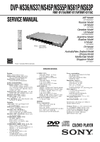
SERVICE MANUAL
Photo : DVP-NS36
RMT-D175P
Notes: Australia/NZ model only
DVP-NS36/NS37/NS45P/NS55P/NS61P/NS63P
RMT-D175A/RMT-D175P/RMT-D175C
AEP Model
DVP-NS36/NS37
Russian Model
UK Model
DVP-NS36
Canadian Model
US Model
DVP-NS45P/NS55P
Argentina Model
Brazilian Model
E Model
DVP-NS63P
PX Model
DVP-NS55P
Australia/New Zealand Model
Chinese Model
Middle East Model
Singapore Model
DVP-NS61P