Sony DVPNS61 Service Manual - Page 5
Service Note
 |
View all Sony DVPNS61 manuals
Add to My Manuals
Save this manual to your list of manuals |
Page 5 highlights
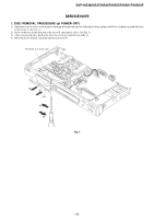
DVP-NS36/NS37/NS45P/NS55P/NS61P/NS63P SERVICE NOTE 1. DISC REMOVAL PROCEDURE (at POWER OFF) 1) Open dust cover to access to a hole insert a tapering driver into the aperture of the unit bottom, and move the lever of chuck can in the direction of the arrow A. (See Fig. 1) 2) Draw out the tray in the direction of the arrow B, and remove a disc. (See Fig. 1) 3) After removing the disc, push in the direction of arrow C until the tray fully in. 4) Move the lever of chuck cam in the direction of arrow D. The lever of a chuck cam Hole B C Tray A D Fig. 1. --55E--
-
 1
1 -
 2
2 -
 3
3 -
 4
4 -
 5
5 -
 6
6 -
 7
7 -
 8
8 -
 9
9 -
 10
10 -
 11
11 -
12
-
13
-
14
-
15
-
16
-
17
-
18
-
19
-
20
-
21
-
22
-
23
-
24
-
25
-
26
-
27
-
28
-
29
-
30
-
31
-
32
-
33
-
34
-
35
-
36
-
37
-
38
-
39
-
40
-
41
-
42
-
43
-
44
-
45
-
46
-
47
-
48
-
49
-
50
-
51
-
52
-
53
-
54
-
55
-
56
-
57
-
58
-
59
-
60
-
61
-
62
-
63
-
64
-
65
-
66
-
67
-
68
-
69
-
70
-
71
-
72
-
73
-
74
-
75
-
76
-
77
-
78
-
79
-
80
-
81
-
82
-
83
-
84
-
85
-
86
-
87
-
88
-
89
-
90
-
91
-
92
-
93
-
94
-
95
-
96
 |
 |

DVP-NS36/NS37/NS45P/NS55P/NS61P/NS63P
SERVICE NOTE
1. DISC REMOVAL PROCEDURE (at POWER OFF)
1)
Open dust cover to access to a hole insert a tapering driver into the aperture of the unit bottom, and move the lever of chuck can in the direction
of the arrow A. (See Fig. 1)
2)
Draw out the tray in the direction of the arrow B, and remove a disc. (See Fig. 1)
3)
After removing the disc, push in the direction of arrow C until the tray fully in.
4)
Move the lever of chuck cam in the direction of arrow D.
The lever of a chuck cam
Hole
Tray
A
D
B
C
Fig. 1.
– 5E –