Sony FWD-42PV1 Operating Instructions - Page 23
Watching the Picture - resolution
 |
View all Sony FWD-42PV1 manuals
Add to My Manuals
Save this manual to your list of manuals |
Page 23 highlights
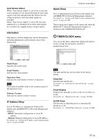
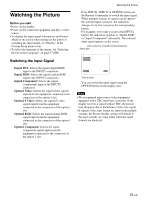
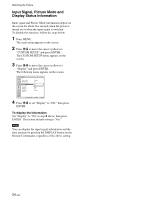
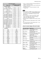
Watching the Picture Before you start • Power on the display. • Power on the connected equipment and play a video source. • To display the input signal information and Picture Mode on the screen when turning on the power or switching the input signal, set "Display" in the Custom Setup menu to On. • To select the language of the menus, see "Selecting the On-screen Language" on page 37 (GB). Switching the Input Signal Input1 DVI: Selects the signal (digital RGB) input to the INPUT1 connectors. Input2 RGB: Selects the signal (analog RGB) input to the INPUT2 connectors. Input2 Component: Selects the signal (component) input to the INPUT2 connectors. Option1 Video: Selects the signal (video signal) input from the equipment connected to the connectors of the option 1 slot. Option1 S Video: Selects the signal (S video signal) input from the equipment connected to the connectors of the option 1 slot. Option1 RGB: Selects the signal (analog RGB signal) input from the equipment connected to the connectors of the option 1 slot. Option1 Component: Selects the signal (component signal) input from the equipment connected to the connectors of the option 1 slot. Watching the Picture Press INPUT1, INPUT2 or OPTION1 button on the Remote Commander to switch the input signal. When multiple formats of signals can be input to the selected input connector, the indication changes every time you press the corresponding button. For example, every time you press the INPUT2 button, the indication switches to "Input2 RGB" or "Input2 Component" alternately. The selected input signal appears on the screen. Color system or resolution/vertical frequency Signal type Input1 DVI 640x480/60 Vivid 15 : 07 Picture mode You can switch the input signal using the OPTION button on the display unit. Notes • We recommend input source video equipment equipped with a TBC (time base corrector). If the display receives a signal without TBC, the picture may disappear due to disturbance of the sync signal. • If signals of the same format are input from multiple systems, the Picture Quality setting will default to the most recently set value (Only when the signal formats are identical). 23 (GB)
-
 1
1 -
2
-
3
-
4
-
5
-
6
-
7
-
8
-
9
-
10
-
11
-
12
-
13
-
14
-
15
-
16
-
17
-
 18
18 -
 19
19 -
 20
20 -
 21
21 -
 22
22 -
 23
23 -
 24
24 -
 25
25 -
 26
26 -
 27
27 -
 28
28 -
29
-
30
-
31
-
32
-
33
-
34
-
35
-
36
-
37
-
38
-
39
-
40
-
41
-
42
-
43
-
44
-
45
-
46
-
47
 |
 |
