Sony FWD-42PV1 Operating Instructions - Page 25
Actual on-screen display of the unit's status
 |
View all Sony FWD-42PV1 manuals
Add to My Manuals
Save this manual to your list of manuals |
Page 25 highlights
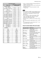
Preset input signals Signal name Color system or horizontal/ vertical frequency Computer signals 1 VGAa)-1 (VGA 350) 31.5 kHz 70 Hz 2 640×480@60 Hz (VESAb) STD) 31.5 kHz 60 Hz 3 Macc) 13" 35.0 kHz 67 Hz 4 VGA (VGA TEXT) 31.5 kHz 70 Hz 5 800×600@60 Hz (VESA STD) 37.9 kHz 60 Hz 6 Mac 16" 49.7 kHz 75 Hz 7 1024×768@60 Hz (VESA STD) 48.4 kHz 60 Hz 8 1024×768@75 Hz (VESA STD) 60.0 kHz 75 Hz 9 1024×768@85 Hz (VESA STD) 68.7 kHz 85 Hz 10 1152×864@75 Hz (VESA STD) 67.5 kHz 75 Hz 11 Mac 21" 68.7 kHz 75 Hz 12 1280×960@60 Hz (VESA STD) 60.0 kHz 60 Hz 13 1280×1024@60 Hz (VESA STD) 64.0 kHz 60 Hz 14 1600×1200@60 Hz (VESA STD)* 75.0 kHz 60 Hz 15 848×480@60 Hz (VESA STD)* 29.8 kHz 60 Hz 16 848×480@60 Hz (VESA STD)** 29.5 kHz 60 Hz 17 848×480@75 Hz* 37.7 kHz 75 Hz 18 1280×768@60 Hz 47.8 kHz 60 Hz 19 1280×768@60 Hz 47.4 kHz 60 Hz SDTV/HDTV 1 PAL PAL 2 NTSC NTSC 3 SECAM SECAM 4 NTSC4.43 NTSC4.43 5 PAL60 PAL60 6 PAL-M PAL-M 7 PAL-N PAL-N 8 575/50i 575/50I 9 480/60i 480/60I 10 1080/24psf 1080/48I 11 1080/50i 1080/50I 12 576/50p 576/50P 13 480/60p 480/60P 14 1080/60i 1080/60I 15 720/60p 720/60P Watching the Picture a) VGA is a registered trademark of International Business Machines Corporation, U.S.A. b) VESA is a registered trademark of the Video Electronics Standards Association. c) Mac (Macintosh) is a registered trademark of Apple Computer, Inc. Notes • When inputting an HDTV signal, input the tri-level sync signal to the 2nd pin of RGB/COMPONENT (D-sub 15 pin) on the INPUT2 connector or the BKM-FW12. • If colors appear too light after inputting a DVD signal to the display unit, adjust the "Chroma" setting in the Adjust Picture menu. • When the phase is readjusted, the resolution will be reduced. • You cannot input the signal indicated with * to DVI IN. • You cannot input the signal indicated with ** to an analog RGB input connectors. Actual on-screen display of the unit's status On-screen display 640×480 / 60 (e.g.) 480 / 60i (e.g.) NTSC (e.g.) Out of Range No Sync INPUT1 DVI INPUT2 RGB INPUT2 Component Option 1 Video Option 1 S Video Option 1 RGB Option 1 Component Significance The selected input signal is computer RGB. The selected input signal is component video. The selected input signal is NTSC. The input signal is out of the capture range. There is no input signal. The signal mode of INPUT1 is set to digital RGB. The signal mode of INPUT2 is set to analog RGB. The signal mode of INPUT2 is set to component video. The signal mode of Option 1 slot is set to composite video. The signal mode of Option 1 slot is set to S VIDEO. The signal mode of Option 1 slot is set to analog RGB. The signal mode of Option 1 slot is set to component video. 25 (GB)
-
 1
1 -
2
-
3
-
4
-
5
-
6
-
7
-
8
-
9
-
10
-
11
-
12
-
13
-
14
-
15
-
16
-
17
-
18
-
19
-
 20
20 -
 21
21 -
 22
22 -
 23
23 -
 24
24 -
 25
25 -
 26
26 -
 27
27 -
 28
28 -
 29
29 -
 30
30 -
31
-
32
-
33
-
34
-
35
-
36
-
37
-
38
-
39
-
40
-
41
-
42
-
43
-
44
-
45
-
46
-
47
 |
 |
