Sony KLV32S400A Revision History
Sony KLV32S400A - 32" Multi-System Dual Voltage HDTV LCD TV Manual
 |
UPC - 011110668585
View all Sony KLV32S400A manuals
Add to My Manuals
Save this manual to your list of manuals |
Sony KLV32S400A manual content summary:
- Sony KLV32S400A | Revision History - Page 1
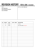
REVISION HISTORY EG1L (GA) CHASSIS MODEL KLV-26S400A KLV-32,32/H/S S400A KLV-37S400A PART NO. : 9-872-993-02 NO. SUFFIX 1 -01 2 -02 DATE 2008/3 2008/4 SUPP / CORR _ _ _ _ DESCRIPTION 1st Issue New model addition. (Page 37) - Sony KLV32S400A | Revision History - Page 2
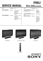
SERVICE MANUAL MODEL KLV-26S400A KLV-32S400A COMMANDER DEST. RM-GA011 RM-GA011 E, EA, India, ME, New Zealand, Philippines, Saudi Arabia, South Africa, Thailand, Vietnam E, EA, India, Iran, ME, New Zealand, Philippines, Saudi Arabia, South Africa, Thailand, Vietnam EG1L (GA)CHASSIS MODEL - Sony KLV32S400A | Revision History - Page 3
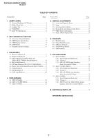
-1 30 7-2-3. BG1, GP, HG4 Boards, Speakers, Bezel Assy and LCD Panel 31 7-3. (KLV-37S400A 32 7-3-1. Rear Cabinet and Stand Assy 32 7-3-2. Chassis-1 33 7-1-3. BG1, Power Unit (G2D), HG4A Boards, Speakers, Bezel Assy and LCD Panel 34 8. ELECTRICAL PARTS LIST 35 OPERATING INSTRUCTIONS - 2 - - Sony KLV32S400A | Revision History - Page 4
VIEWS ARE CRITICAL FOR SAFE OPERATION. REPLACE THESE COMPONENTS WITH SONY PARTS WHOSE PART NUMBERS APPEAR AS SHOWN IN THIS MANUAL OR IN SUPPLEMENTS PUBLISHED BY SONY. CIRCUIT ADJUSTMENTS THAT ARE CRITICAL FOR SAFE OPERATION ARE IDENTIFIED IN THIS MANUAL. FOLLOW THESE PROCEDURES WHENEVER CRITICAL - Sony KLV32S400A | Revision History - Page 5
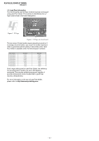
KLV-26,32,32/H/S,37 S400A RM-GA011 1-5. Lead Free Information The circuit boards used in these models have been processed using Lead Free Solder. The boards are identified by the LF logo located close to the board designation. Figure 2: LF logo Figure 3: LF logo on circuit board The servicing of - Sony KLV32S400A | Revision History - Page 6
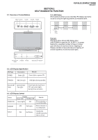
KLV-26,32,32/H/S,37 S400A RM-GA011 SECTION 2 SELF DIAGNOSTIC FUNCTION 2-1. Overview of Control Buttons MENU TV/VIDEO VOLUME CHANNEL POWER state types. PICTURE OFF/ STANDBY POWER TIMER REMOTE/LIGHT SENSOR 2-2. LED Display Specification LED Type Description Remark POWER Green: LED Green - Sony KLV32S400A | Revision History - Page 7
KLV-26,32,32/H/S,37 S400A RM-GA011 2-5. Standby LED Error Display Perform below countermeasures according to Standby LED blinking times. Blinking times Error Countermeasure 2 DC_DET (12V Main Voltage) Replace either/both z BG1 board z GP(26",32")/ Power Unit(G2D)(37") board 3 DC_ALERT 1 - Sony KLV32S400A | Revision History - Page 8
X 16) 2 Two screws (+BVTP 3 X 12) 3 One screw (+PSW M5 X 8) 5 Lift to remove Rear Cover 3-2. Stand Assy Removal (KLV-26S400A) 1 Three screws (+PSW M5 X 16) 2 Stand assy (KLV-32,32/H/S S400A) 4 Two screws (+PSW M3 X 5) 1 Sixteen screws (BVTP2 4 X 16) 2 Two screws (+BVTP 3 X 12) 3 One screw (+PSW - Sony KLV32S400A | Revision History - Page 9
screws (+BVTP2 3 X 12) 6 HG4 board 4 One connector Guide Light Bezel assy (KLV-32,32/H/S S400A) 2 Harness with connector 1 Two screws (+BVTP2 4 X 16) 3 LCD panel 5 Two screws (+BVTP2 3 X 12) 6 HG4 board 4 One connector Guide Light Bezel assy 3-4. BG1 Board Removal (KLV-26S400A) 1 One screw (+PSW - Sony KLV32S400A | Revision History - Page 10
3-5. GP Board Removal (KLV-26,32,32/H/S S400A) 1 Four screws (+PSW 3SG) 2 One connector 3 GP board G1 Bracket KLV-26,32,32/H/S,37 S400A RM-GA011 (KLV-32,32/H/S S400A) 4 One screw (+PSW M4 X 8) 5 One screw (+PSW M4 X 8) 2 Two screws (+PSW M4 X 8) Vesa Frame (Top) Assy 6 One screw (+PSW M4 X 8) - Sony KLV32S400A | Revision History - Page 11
32,32/H/S,37 S400A RM-GA011 (KLV-32,32/H/S S400A) Speaker (KLV-32,32/H/S S400A) 2 Harness with connector 1 Two screws (+BVTP2 4 X 16) 3 Lift to remove LCD panel Bezel assy (KLV-37S400A) Speaker Bezel assy (KLV-37S400A) 2 Six screws (+BVTP2 4 X 16) 1 Harness with connector 3 Lift to remove LCD - Sony KLV32S400A | Revision History - Page 12
DRESSING KLV-26,32,32/H/S,37 S400A RM-GA011 CAUTION : 1. Do not overpull the wires during dressing --> avoid disconnection of wires. 2. Make sure wires are kept away from sharp edges, heatsinks & other high-temperature parts. 4-1-2. Wire Dressing Overview for CISPR model. 4-1-3. Dress LVDS cable - Sony KLV32S400A | Revision History - Page 13
KLV-26,32,32/H/S,37 S400A RM-GA011 4-1-5. Dress Connector Assy 13P at G1 bracket's hook, Assy 14P+20P & Speaker Wire with Sheet Core C (quantity: 2). 4-1-10. Apply Sheet Core C on LCD panel and dress Connector Assy 14P+20P & Speaker Wire with Sheet Core C. Connector assy 14P+20P Sheet Core - Sony KLV32S400A | Revision History - Page 14
with LCD tape. KLV-26,32,32/H/S,37 S400A RM-GA011 4-1-12. Dress Connector Assy 14P+20P with LCD tape. LCD tape Datum Speaker Wire Screw boss Caution : Pull away from screw boss Connector assy 14P+20P Datum LCD tape 4-1-13. Install AC Cord Holder on AC Power Cord. (For Non-CISPR model) 4-1-14 - Sony KLV32S400A | Revision History - Page 15
KLV-26,32,32/H/S,37 S400A RM-GA011 4-2. (KLV-32,32/H/S S400A) 4-2-1. Wire Dressing Overview for Non-CISPR model 4-2-2. Wire Dressing Overview for CISPR model 4-2-3. Dress LVDS Cable with Sheet Core C (quantity: 2). (For Non-CISPR model) Make sure LVDS connector fully inserted with correct - Sony KLV32S400A | Revision History - Page 16
cable with Sheet Core C & Shield Tape. (For CISPR model) KLV-26,32,32/H/S,37 S400A RM-GA011 4-2-5. Screw LVDS cable's clamp on main bracket. (For CISPR model) Apply tape at the middle of this area. LVDS cable Datum LVDS cable LVDS cable's clamp Shield Tape Sheet Core C Datum 4-2-6. Dress - Sony KLV32S400A | Revision History - Page 17
KLV-26,32,32/H/S,37 S400A RM-GA011 4-2-10. Dress Connector Assy 14P+20P & Speaker wire with Sheet Core C (quantity: 2) Speaker Wire Connector assy 14P+20P Sheet Core C Datum Datum 4-2-11. Apply Sheet Core C on LCD Panel and dress Connector Assy 14P+20P & Speaker Wire with Sheet Core C and Slide - Sony KLV32S400A | Revision History - Page 18
4-3. (37S400A) 4-3-1. Wire Dressing Overview for Non-CISPR model. KLV-26,32,32/H/S,37 S400A RM-GA011 4-3-2. Wire Dressing Overview for CISPR model. 4-3-3. Dress LVDS cable with G2 bracket (upper)'s hook. (For Non-CISPR model) Make sure LVDS connector fully inserted with correct direction as shown - Sony KLV32S400A | Revision History - Page 19
KLV-26,32,32/H/S,37 S400A RM-GA011 4-3-7. Apply Sheet Core C on LCD panel and dress Connector Assy 14P+20P & Speaker Wire with sheet core C. Sheet Core C Connector assy 14P+20P Datum Datum Datum Follow White UL tape as guide to apply tape Speaker Wire Caution : Pull away from screw boss Screw - Sony KLV32S400A | Revision History - Page 20
Clamp (quantity: 2) Connector assy 14P+20P KLV-26,32,32/H/S,37 S400A RM-GA011 4-3-10. Dress Connector Assy 14P+20P on top of Connector Assy 13P. Connector assy 14P+20P Pull wire straight Connector assy 13P 4-3-11. Dress Connector Assy 14P+20P with LCD tape. 4-3-12. Dress Connector Assy 14P+20P - Sony KLV32S400A | Revision History - Page 21
KLV-26,32,32/H/S,37 S400A RM-GA011 4-3-15. Dress Connector Assy 14P+20P with LCD tape (quantity: 2) Connector assy 14P+20P Datum 4-3-16. Install AC Cord Holder on AC Power Cord (For Non-CISPR model) AC Cord holder AC Power Cord 130mm LCD tape Datum 4-3-17. Install AC Cord Holder on AC Power Cord - Sony KLV32S400A | Revision History - Page 22
5 SERVICE ADJUSTMENTS KLV-26,32,32/H/S,37 S400A RM-GA011 5-1. Accessing Diagnostic Menu 5-3. Accessing Service Menu 1. While TV set on standby, press the following sequence on 1. While TV set on standby, press the following sequence on the remote commander (RM-GA011). the remote commander - Sony KLV32S400A | Revision History - Page 23
KLV-26,32,32/H/S,37 S400A RM-GA011 5-4. Resetting the User Menu - Factory Reset Note: The TEST RESET option resets all the customer adjustable data back to factory defaults. 1. While TV set on standby, press the following sequence on the remote commander (RM-GA011). On screen display Channel 5 - Sony KLV32S400A | Revision History - Page 24
KLV-26,32,32/H/S,37 S400A RM-GA011 mode. (Power OFF). 9. Access the service menu. 10. The service menu displays. Service Menu Status W/B Service Figure 12 11. Press the 'down' 451mv 5-6. Board & Panel Replacement When replacing the BG1 board and Panel, make sure to readjust the W/B. - 23 - - Sony KLV32S400A | Revision History - Page 25
BLOCK DIAGRAM SECTION 6 DIAGRAMS Due to complexity of the board, performing component level field repairs are not recommended. Complete board replacement is required if service is necessary. 6-2. CIRCUIT BOARD LOCATION KLV-26,32,32/H/S,37 S400A BG1 Board Block Switch Panel GP Board (KLV-26,32,32 - Sony KLV32S400A | Revision History - Page 26
KLV-26,32,32/H/S,37 S400A RM-GA011 6-3. SCHEMATIC DIAGRAM 6-4. PRINTED WIRING BOARDS HG4 (KLV-26,32,32/H/S S400A), HG4A (KLV-37S400A), BG1, GP (KLV-26,32,32/H/S S400A), POWER UNIT (G2D) (KLV-37S400A) Boards. Board Function Note BG1 GP POWER UNIT (G2D) HG4/HG4A I/O/Audio/VCTP/DDR/HDMI/ DC-DC - Sony KLV32S400A | Revision History - Page 27
KLV-26,32,32/H/S,37 S400A RM-GA011 SECTION 7 EXPLODED VIEWS • Components not identified by a part number or description are not stocked because they are not required for routine service. • The component parts of an assembly are indicated by the reference numbers in the far right column of the - Sony KLV32S400A | Revision History - Page 28
CHASSIS 1 KLV-26,32,32/H/S,37 S400A RM-GA011 f f b b f b b b f 51 52 50 REF. NO. PART NO. DESCRIPTION REMARK 50 ! 1-835-136-11 POWER SUPPLY CORD (WITH CONNECTOR) (Except KLV-26S400A(India, New Zealand, Thailand)) ! 1-835-280-11 POWER SUPPLY CORD (WITH CONNECTOR) (KLV-26S400A(India - Sony KLV32S400A | Revision History - Page 29
A-1539-291-A BG1 MOUNT(SERVICE) (KLV-26S400A(New Zealand)) 103 * 1-480-889-01 BLOCK SWITCH PANEL 104 3-290-408-01 GUIDE, LIGHT 105 1-826-648-21 LOUD SPEAKER (4.2 X 15CM) 106 ! 1-802-613-11 LCD PANEL (26INCH WXGA TFT) 107 X-2189-890-01 BEZEL(26) ASSY 108 4-103-599-21 EMBLEM, SONY NO.7 109 - Sony KLV32S400A | Revision History - Page 30
i REF. NO. PART NO. DESCRIPTION REMARK 1 X-2189-524-1 REAR COVER(32) ASSY 2 * 3-106-086-02 COVER, ECS * 3-106-086-03 COVER, ECS (KLV-32S400A(Iran)) 3 X-2189-640-2 STAND (M-2) ASSY (KLV-32S400A) X-2318-469-1 STAND (M-2)(S) ASSY (KLV-32S400A/S) X-2318-465-1 STAND (M-2)(H) ASSY (KLV-32S400A - Sony KLV32S400A | Revision History - Page 31
-11 POWER SUPPLY CORD (WITH CONNECTOR) (Except KLV-32(India,New Zealand,Thailand), 32/H(India),32/H(Thailand) S400A) ! 1-835-280-11 POWER SUPPLY CORD (WITH CONNECTOR) (KLV-32(India),32/H(India) S400A) ! 1-835-128-11 POWER SUPPLY CORD (WITH CONNECTOR) (KLV-32S400A(New Zealand)) ! 1-835-127-11 - Sony KLV32S400A | Revision History - Page 32
101 b b g REF. NO. PART NO. DESCRIPTION REMARK 101 A-1540-080-A GP COMPL KIT(32) (Except KLV-32S400A(New Zealand)) A-1539-154-A GP COMPL (32) (KLV-32S400A(New Zealand)) 102 A-1527-549-A BG1 MOUNT (SERVICE) 103 A-1527-469-A HG4 MOUNT 104 3-290-408-01 GUIDE, LIGHT 105 1-826-648-21 LOUD - Sony KLV32S400A | Revision History - Page 33
KLV-26,32,32/H/S,37 S400A RM-GA011 7-3 (KLV-37S400A) 7-3-1. REAR CABINET AND STAND ASSY f a 2-580-591-01 b SCREW, PSW M5X20 SCREW, +K M3X8 f f a k f m 2 1 n j j 3 g 4 i REF. NO. PART NO. DESCRIPTION 1 X-2190-009-1 REAR COVER(37) ASSY 2 * 3-106-086-03 COVER, ECS 3 X-2189-979-2 STAND(ML-2) - Sony KLV32S400A | Revision History - Page 34
KLV-26,32,32/H/S,37 S400A RM-GA011 f b f c b c f c c b b f 53 54 52 51 REF. NO. PART NO. DESCRIPTION REMARK 51 ! 1-835-136-11 POWER SUPPLY CORD (WITH CONNECTOR) (Except KLV-37S400A(India,New Zealand,Thailand)) ! 1-835-280-11 POWER SUPPLY CORD (WITH CONNECTOR) (KLV-37S400A(India - Sony KLV32S400A | Revision History - Page 35
KLV-26,32,32/H/S,37 S400A RM-GA011 7-3-3. BG1, POWER UNIT (G2D), HG4A BOARDS, SPEAKERS, BEZEL ASSY AND LCD PANEL 108 106 107 104 105 101 f 109 a 102 103 k e e f 110 c c e REF. NO. PART NO. DESCRIPTION REMARK 101 A-1527-549-A BG1 MOUNT (SERVICE) (Except KLV-37S400A(New Zealand)) A-1539- - Sony KLV32S400A | Revision History - Page 36
26S400A(New Zealand)) GP COMPL KIT (32) (Except KLV-32S400A(New Zealand)) GP COMPL (32) (KLV-32S400A(New Zealand)) POWER, UNIT (G2D board) (KLV-37S400A REF NO. PART NO. DESCRIPTION REMARK 1-966-103-21 1-966-102-21 HARNESS WITH CONNECTOR (LVDS) (Except KLV-37S400A(New Zealand)) CN3002(BG1)-TCON - Sony KLV32S400A | Revision History - Page 37
MOUNT) KLV-32S400A(Iran),37S400A(Iran)) INSTRUCTION (WALL MOUNT) (KLV-32S400A(Vietnam),37S400A(Vietnam)) REF NO. PART NO. DESCRIPTION REMARK 3-293-038-11 3-293-038-21 3-293-038-31 3-293-038-41 3-293-042-11 MANUAL, INSTRUCTION (KLV-26S400A(E,EA,India,New Zealand,Saudi Arabia), 32(E,EA,India,New - Sony KLV32S400A | Revision History - Page 38
in the original issue. SECTION 3. DISASSEMBLY 3-3. HG4A Board Removal (refer page 8) 2 Harness with connector 1 Two screws (+BVTP2 4 X 16) 3 LCD panel 5 Two screws (+BVTP2 3 X 12) 6 HG4A board 4 One connector Guide Light Bezel assy SECTION 6. DIAGRAMS 6-2. Circuit Board Location (refer page 24) HG4A - Sony KLV32S400A | Revision History - Page 39
038-43 4-108-226-11 CUSHION, UPPER CUSHION, LOWER INDIVIDUAL CARTON INSTRUCTION (WALL MOUNT) MANUAL, INSTRUCTION MANUAL, INSTRUCTION MANUAL, INSTRUCTION MANUAL, INSTRUCTION (WALL MOUNT) 9-872-993-02 Sony Corporation Sony EMCS (Malaysia) Sdn. Bhd. TV Operations of Pan Asia - 38 - English 2008.4 - Sony KLV32S400A | Revision History - Page 40
KLV-40S400A KLV-37S400A KLV-32S400A KLV-26S400A © 2008 Sony Corporation LCD Colour TV Operating Instructions 3-293-038-11(1) 3-293-038-11(1) - Sony KLV32S400A | Revision History - Page 41
Introduction Thank you for choosing this Sony product. Before operating the TV, please read this manual thoroughly and retain it for future reference. The illustrations used in this manual are of the KLV-32S400A unless otherwise stated. Trademark information • HDMI, the HDMI logo and High- - Sony KLV32S400A | Revision History - Page 42
28 Channel Set-up menu 30 32 Additional Information Specifications 32 Troubleshooting 33 Connecting optional equipment 15 Viewing pictures from the connected equipment 16 Viewing Twin Picture 17 Viewing PIP (Picture in Picture 17 Using BRAVIA Sync (Control for HDMI) ... 18 To connect the - Sony KLV32S400A | Revision History - Page 43
Start-up Guide Checking the accessories AC power cord* (KLV-40S400A only) Stand (1) and screws (3) Remote RM-GA011 (1) Size AA batteries (R6 type) (2) * For models with ferrite cores, do not remove these cores. Inserting batteries into the remote Push and lift the cover to open. 1: Attaching the - Sony KLV32S400A | Revision History - Page 44
Start-up Guide 2: Connecting an antenna/cable/VCR Connecting an antenna/cable 3: Preventing the TV from toppling over 8 Antenna cable (not supplied) 8 Connecting an antenna/cable and VCR Audio/Video cable (not supplied) 8 8 Antenna cable (not supplied) S video cable (not - Sony KLV32S400A | Revision History - Page 45
the AC power cord BRAVIA Sync SYNC MENU THEATRE AUDIO 3, 4, 5, 6, 9, RETURN TOOLS 10, 11 8 KLV-40S400A KLV-37/32/26S400A * Type TV. When the TV is in standby mode (the 1 (standby) indicator on the TV front panel is red), press "/1 on the remote to turn on the TV. When you turn on the TV - Sony KLV32S400A | Revision History - Page 46
operations of the TV and the connected equipment that is compatible with control for HDMI automatically. Do you want to enable control for compatible HDMI devices? Auto-tuning the TV be patient and do not press any buttons on the TV or remote. If a message appears for you to confirm the antenna - Sony KLV32S400A | Revision History - Page 47
, refer to the instruction guide provided by the Wall-Mount Bracket model for your TV. Sufficient expertise is required in installing this TV, especially to determine the strength of the wall for withstanding the TV's weight. For product protection and safety reasons, Sony strongly recommends that - Sony KLV32S400A | Revision History - Page 48
down and cause personal injury or damage to the TV. • Only qualified service personnel should carry out wall installations. • For safety reasons, it is strongly recommended that you use Sony accessories, including: - KLV-40S400A/KLV-37S400A/KLV-32S400A: Wall-mount bracket SU-WL500 and SU-WL50B - Sony KLV32S400A | Revision History - Page 49
TV shall not problems occur. Ask your dealer or Sony service centre to have it checked by qualified service personnel. When: - AC power cord is damaged. - Poor fitting of AC power outlet. - TV TV • View the TV in moderate light, as viewing the TV LCD screen. This is a structural property of the LCD - Sony KLV32S400A | Revision History - Page 50
on and off from standby mode. 2 BRAVIA Sync (page 18) • m/N/X/M/x: You can operate the BRAVIA Sync-compatible equipment that is connected to the TV. • SYNC MENU: Displays the menu of connected HDMI CEC (Consumer Electronics Control) equipment which is supported. While viewing other input screens or - Sony KLV32S400A | Revision History - Page 51
BRAVIA the TV picture (mix mode) t No Text (exit the Text service). ~ desired wide mode. For TV, Video, HD/DVD or HDMI (except Full Stretches the 4:3 picture horizontally, to fill the 16:9 screen. Zoom* Displays cinemascopic (letter box format) broadcasts in the correct proportions. * Parts - Sony KLV32S400A | Revision History - Page 52
. Horizontal Shift (in PC input mode only) See page 29. Sleep Timer (except PC input mode) See page 28. Power Saving See page 28. Device Control [in HDMI input mode (except HDMI PC input) only] Displays the menu screen to operate the connected HDMI-compatible equipment. 13 GB - Sony KLV32S400A | Revision History - Page 53
amber when the timer is set (page 28). 7 1 - Standby indicator Lights up in red when the TV is in standby mode. 8 " - Power indicator • Lights up in green when the TV is turned on. • Flashes while the remote is being operated. 9 - Remote sensor / Light sensor (page 28) • Receives IR signals from the - Sony KLV32S400A | Revision History - Page 54
Using Optional Equipment Connecting optional equipment You can connect a wide range of optional equipment to your TV. For service use only Audio system DVD player S VHS/Hi8/ DVC camcorder PC (HDMI output) Blu-ray disc player Headphones Digital video camera Using Optional Equipment PC - Sony KLV32S400A | Revision History - Page 55
any operation after pressing control for HDMI, communication with the connected equipment is supported logo (recommended Sony HDMI cable). TV speakers, set "Speaker" to "Audio System" (page 27). If you connect mono equipment, connect to the L jack . ~ • The monitor output jacks cannot support HD - Sony KLV32S400A | Revision History - Page 56
. Left Window Right Window Twin Picture Availability In Left Window In Right Window HD/DVD 1 HD/DVD 2 HDMI 1 (except PC input mode) HDMI 2 (except PC input mode) HDMI 3 (except PC input mode) TV programme Video 1 or S Video 1 Video 2 Video 3 No picture 2 Press G/g to select active picture - Sony KLV32S400A | Revision History - Page 57
audio system. • You can operate the connected Sony equipment that has the BRAVIA Sync logo by the TV remote by pressing: - N/x/X/m/M to operate the connected equipment directly. - SYNC MENU to display the menu of the connected HDMI CEC equipment which is supported on the screen. After displaying - Sony KLV32S400A | Revision History - Page 58
BRAVIA Sync SYNC MENU THEATRE AUDIO "MENU" allows you to enjoy various convenient features of this TV. You can easily select channels or inputs sources and change the settings for your TV favourite list is full, select "Edit Favourites equipment that is compatible with control for HDMI, select "HDMI - Sony KLV32S400A | Revision History - Page 59
from a list of up to 16 favourite channels that you specify. 1 Press MENU. 2 Press F/f to select "Favourites", then press . 3 Perform the desired operation as shown in the following table or displayed on the screen. Favourite List To Watch a channel Turn off the Favourite list Add a current channel - Sony KLV32S400A | Revision History - Page 60
Shift Vertical Shift Vertical Size TV Wide Zoom Full Pixel 0 0 Screen menu (page 25) "Wide Mode": "Wide Zoom" t "Normal" t "Full" t "Zoom" "Auto Wide": "On" t "Off" "4:3 Default": "Wide Zoom" t "Normal" t "Off" "Display Area": "Full Pixel" t "Normal" (KLV-40S400A only) "Horizontal Shift" "Vertical - Sony KLV32S400A | Revision History - Page 61
1" t "Full 2" "Reset" "Auto Adjustment" "Phase" "Pitch" "Horizontal Shift" "Power Management": "On" t "Off" Channel Set-up TV 1 Digit Direct Off Favourite Set-up Auto Tuning Programme Sorting Programme Labels Programme Block Intelligent Picture On Manual Programme Preset Select: Set - Sony KLV32S400A | Revision History - Page 62
Using MENU Functions Picture menu Press MENU and select "Settings". Make sure the "Picture" icon ( ) is selected, then press . Picture Mode Display Mode Reset Backlight Selects the picture mode except for PC input source. "Vivid": For enhanced picture contrast and sharpness. "Standard": For - Sony KLV32S400A | Revision History - Page 63
Sound menu Press MENU and select "Settings". Press F/f to select the "Sound" icon ( ), then press . Sound Mode Reset Treble Bass Balance Intelligent Volume Volume Offset Surround Voice Zoom Sound Booster "Dynamic": Enhances treble and bass. Recommended for home entertainment. "Standard": For - Sony KLV32S400A | Revision History - Page 64
external equipment. To keep your setting, select "Off". ~ • "Auto Wide" is not available when watching TV programmes. z • Even if "Auto Wide" is set to "On" or "Off", you can always is set to "On". • "4:3 Default" is not available when watching TV programmes or for a HD input signal. Continued 25 GB - Sony KLV32S400A | Revision History - Page 65
parts of the picture are cut off. "Normal": Displays the recommended picture area. ~ • "Display Area" is available only when "Wide Mode" is set to "Full operation because it was done when the TV was first installed (page 6). However, this option allows you to repeat the process (e.g. to retune the TV - Sony KLV32S400A | Revision History - Page 66
HDMI Sets whether or not to link the operations of the TV and the connected equipment that is compatible with control for HDMI. When set to "On", the following menu items can be performed. If the specific Sony equipment that is compatible with control for HDMI is connected, this setting is applied - Sony KLV32S400A | Revision History - Page 67
TV. "Duration": Selects the time period after which the TV automatically switches to standby mode again. Clock Set Allows you to adjust the clock manually. page 13. "Full 1": Enlarges the picture to fill the display area, keeping its original horizontalto-vertical aspect ratio. "Full 2": Enlarges - Sony KLV32S400A | Revision History - Page 68
60 60 Standard VGA VESA VGA-T VESA Guidelines VESA VESA Guidelines VESA VESA VESA VESA VESA ~ • This TV's PC input does not support Sync on Green or Composite Sync. • This TV's PC input does not support interlaced signals. • If input signal is not shown in above chart, then this signal may not be - Sony KLV32S400A | Revision History - Page 69
you cannot select channel numbers 10 and above entering two digits using the remote. Allows you to set your favourite channels by assigning the desired channel by broadcasters. Changes the order in which the channels are stored on the TV. 1 Press F/f to select the channel you want to move to a new - Sony KLV32S400A | Revision History - Page 70
select a programme number that is set to "Skip" (page 31). Programme/TV System/VHF or UHF Presets programme channels manually. 1 Select "Programme", then press . 2 Press F/f to select the programme number you want to manually tune (if tuning a VCR, select channel 00), then press RETURN. 3 Press - Sony KLV32S400A | Revision History - Page 71
Specifications Model name KLV-40S400A KLV-37S400A KLV-32S400A KLV-26S400A System Panel System LCD (Liquid Crystal Display) Panel TV : 47 kilohms 1, 2 1, 2 Supported formats: 1080p (50/60 Hz), 1080i Two channel linear PCM 32, 44.1 and 48 ohms/ R: 0.7 Vp-p, 75 ohms/HD: 1-5 Vp-p/VD: 1-5 Vp-p PC - Sony KLV32S400A | Revision History - Page 72
problem while viewing your TV, you can either check the Troubleshooting guide below or use the "Factory Settings" function (page 28). If the problem persists, contact your Sony TV to turn it off, disconnect the AC power cord, and inform your dealer or Sony service • Select "Manual Programme Preset" - Sony KLV32S400A | Revision History - Page 73
Problem Good picture, but noisy sound Cause/Remedy • The TV Manual Programme Preset" in the "Channel Set-up" menu, and select the appropriate TV system ("TV TV, VCR, and on the wall (page 5). • Adjust the antenna direction for the minimum interference. Contact a Sony 26). The remote does not function - Sony KLV32S400A | Revision History - Page 74
may improve the picture (page 31). • Some shooting games which involve pointing a light beam at the TV screen with an electronic gun or rifle cannot be used with your TV. For details, see the instruction manual supplied with the video game software. • Changes in room temperature sometimes make the - Sony KLV32S400A | Revision History - Page 75
Customer support (1) Printed in Malaysia - Sony KLV32S400A | Revision History - Page 76
KLV-26S400A Installing the Wall-Mount Bracket GB CT AR PR © 2008 Sony Corporation * 3 2 9 3 0 4 2 1 1 * (1) 3-293-042-11(1) - Sony KLV32S400A | Revision History - Page 77
your TV's model number and be sure to use the bracket specified for your model only. Refer to the steps on this manual along with the Instructions supplied with for withstanding the TV's weight. Be sure to entrust the attachment of this product to the wall to Sony dealers or licensed contractors - Sony KLV32S400A | Revision History - Page 78
× 12) Mounting Hook GB Soft cloth Notes • When removing the Table-Top Stand from the TV, lay the display face down on a stable work surface that is larger than the TV. • To prevent damaging the surface of the LCD display, make sure to place a soft cloth on the work surface. Soft cloth Notes - Sony KLV32S400A | Revision History - Page 79
Be sure that both screws are tightened securely with equal torque strength to the rear of the TV. If you adjusted the left angle of the Mounting Hook, also perform the same adjustment as in screwed in securely. Step 6: Installing the TV on the wall Refer to the Instructions for the SU-WL100. 4 (GB) - Sony KLV32S400A | Revision History - Page 80
dimensions table AR PR Unit: mm Model Name/ Display dimensions/ Screen centre dimension/ Length for each mounting angle/ Angle (0o)/ Angle (20o)/ A B C KLV-26S400A 675 466 83 Installation dimensions may differ according to how the TV is installed. D E F G H 335 157 269 439 - Sony KLV32S400A | Revision History - Page 81
Hook location a b* Model Name KLV-26S400A * Hook position "b" cannot be used for the models in the table below. * * * Hook location a Printed in Malaysia
-
 1
1 -
 2
2 -
 3
3 -
 4
4 -
 5
5 -
 6
6 -
 7
7 -
8
-
9
-
10
-
11
-
12
-
13
-
14
-
15
-
16
-
17
-
18
-
19
-
20
-
21
-
22
-
23
-
24
-
25
-
26
-
27
-
28
-
29
-
30
-
31
-
32
-
33
-
34
-
35
-
36
-
37
-
38
-
39
-
40
-
41
-
42
-
43
-
44
-
45
-
46
-
47
-
48
-
49
-
50
-
51
-
52
-
53
-
54
-
55
-
56
-
57
-
58
-
59
-
60
-
61
-
62
-
63
-
64
-
65
-
66
-
67
-
68
-
69
-
70
-
71
-
72
-
73
-
74
-
75
-
76
-
77
-
78
-
79
-
80
-
81
 |
 |
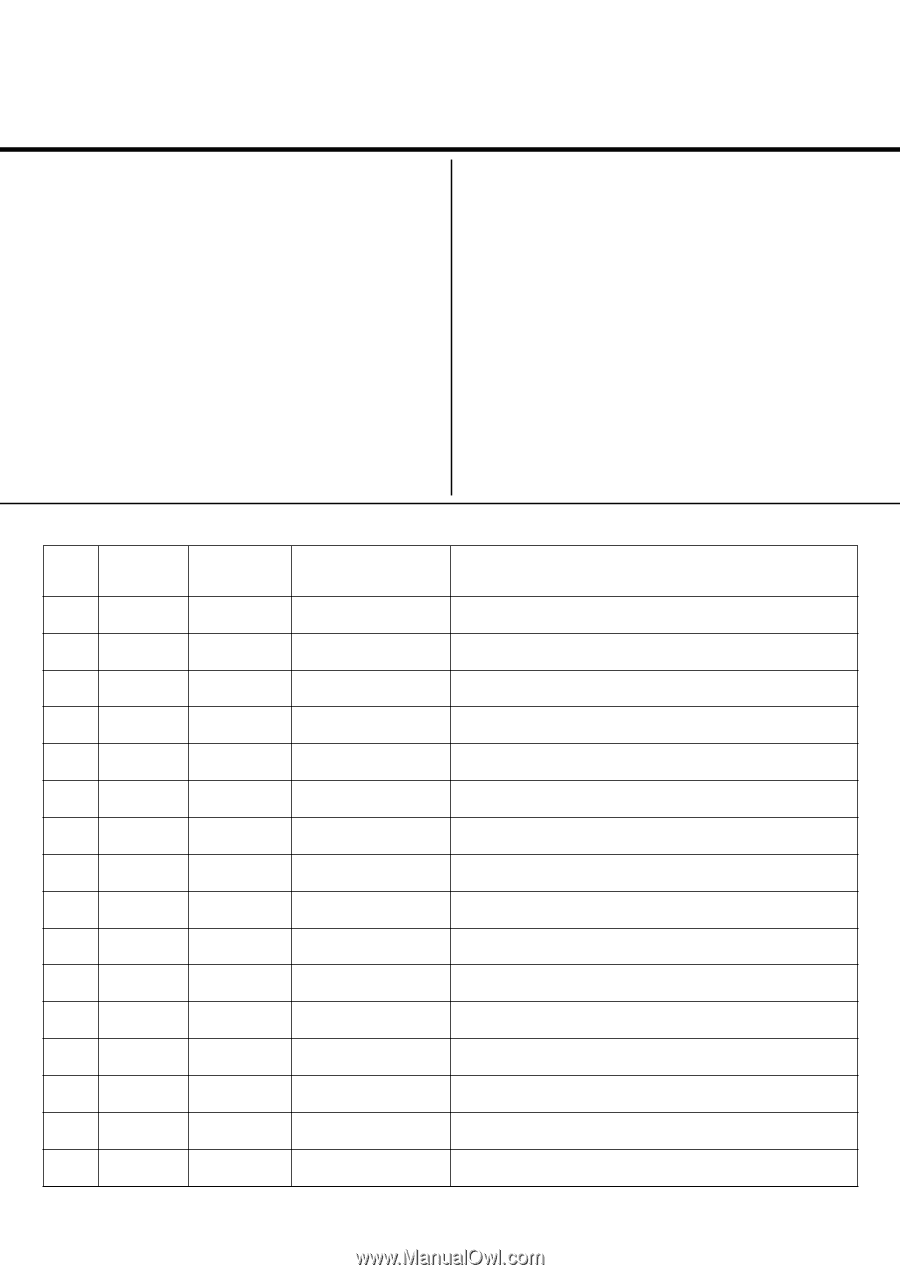
REVISION HISTORY
NO.
SUFFIX
DATE
SUPP / CORR
DESCRIPTION
1
-01
2008/3
_ _
1st Issue
2
-02
2008/4
_ _
New model addition.
(Page 37)
EG1L (GA)
CHASSIS
MODEL
KLV-26S400A
KLV-32,32/H/S S400A
KLV-37S400A
PART NO.:
9-872-993-02