Sony KLV32S400A Revision History - Page 27
Exploded Views, (klv-26s400a), Rear Cabinet And Stand Assy
 |
UPC - 011110668585
View all Sony KLV32S400A manuals
Add to My Manuals
Save this manual to your list of manuals |
Page 27 highlights
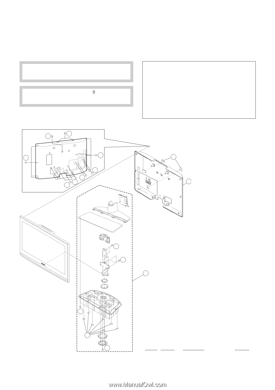
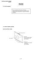
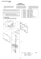
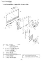
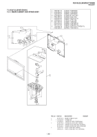
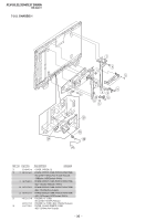
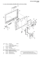
KLV-26,32,32/H/S,37 S400A RM-GA011 SECTION 7 EXPLODED VIEWS • Components not identified by a part number or description are not stocked because they are not required for routine service. • The component parts of an assembly are indicated by the reference numbers in the far right column of the part list and within the dotted lines of the diagram. NOTE: The components identified by shading and ! mark are critical for safety. Replace only with part number specified. Note: The components identified by mark contain confidential information. Strictly follow the instructions whenever the components are repaired and /or replaced. 7-1 (KLV-26S400A) 7-1-1. REAR CABINET AND STAND ASSY a 2-580-591-01 b 2-580-600-01 c 2-580-606-01 d 2-580-626-01 e 2-580-629-01 f 2-580-640-01 g 2-580-644-01 h 2-674-965-31 i 3-873-012-01 j 3-873-013-01 k 7-685-648-79 l 2-580-608-01 • Item marked with an asterisk (*) are not stocked since they are seldom required for routine service. Some delay should be anticipated when ordering these components. SCREW, +PSW M3X5 SCREW, +PSW M4X8 SCREW, +PSW M5X8 SCREW, SP 4-4O UNC SCREW, +BVST 3X8 SCREW, +BVTP2 4X16 SCREW, +KTP2 3X8 SCREW, +PSW 3SG SCREW, +PWH M5X16 SCREW, +PWH M5X10 SCREW, +BVTP 3X12 TYPE2 IT-3 SCREW +PSW M5 X 16 c f f f a k f l 2 1 j j 3 g 4 i REF. NO. PART NO. DESCRIPTION 1 X-2189-891-1 REAR COVER(26) ASSY 2 * 3-106-086-02 COVER, ECS 3 X-2189-640-2 STAND (M-2) ASSY 4 3-700-532-01 FOOT (15X20) - 26 - REMARK
-
 1
1 -
2
-
3
-
4
-
5
-
6
-
7
-
8
-
9
-
10
-
11
-
12
-
13
-
14
-
15
-
16
-
17
-
18
-
19
-
20
-
21
-
 22
22 -
 23
23 -
 24
24 -
 25
25 -
 26
26 -
 27
27 -
 28
28 -
 29
29 -
 30
30 -
 31
31 -
 32
32 -
33
-
34
-
35
-
36
-
37
-
38
-
39
-
40
-
41
-
42
-
43
-
44
-
45
-
46
-
47
-
48
-
49
-
50
-
51
-
52
-
53
-
54
-
55
-
56
-
57
-
58
-
59
-
60
-
61
-
62
-
63
-
64
-
65
-
66
-
67
-
68
-
69
-
70
-
71
-
72
-
73
-
74
-
75
-
76
-
77
-
78
-
79
-
80
-
81
 |
 |