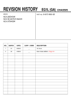
Sony KLV32S400A Revision History - Page 3
Table Of Contents - specifications
 |
UPC - 011110668585
View all Sony KLV32S400A manuals
Add to My Manuals
Save this manual to your list of manuals |
Page 3 highlights
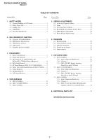
KLV-26,32,32/H/S,37 S400A RM-GA011 TABLE OF CONTENTS Section Title Page Section Title Page 1. SAFETY NOTES 1-1. Caution Handling of LCD Panel 3 1-2. Safety Check Out 3 1-3. Leakage Test 3 1-4. WARNING 3 1-5. Lead Free Information 4 5. SERVICE ADJUSTMENTS 5-1. Accessing Diagnostic Menu 21 5-2. Aging 21 5-3. Accessing Service Menu 21 5-4. Resetting the User Menu- Factory Reset 22 5-5. White Balance Adjustment 22 5-6. Board & Panel Replacement 23 2. SELF DIAGNOSTIC FUNCTION 2-1. Overview of Control Buttons 5 2-2. LED Display Specification 5 2-3. LED Display Control 5 2-4. LED Pattern 5 2-5. Standby LED Error Display 6 6. DIAGRAMS 6-1. Block Diagram 24 6-2. Circuit Board Location 24 6-3. Schematic Diagram 25 6-4. Printed Wiring Boards 25 6-5. Semiconductor 25 3. DISASSEMBLY 3-1. Rear Cover Removal 7 3-2. Stand Assy Removal 7 3-3. HG4 (KLV-26,32,32/H/S S400A) and HG4A (KLV-37S400A) Boards Removal 8 3-4. BG1 Board Removal 8 3-5. GP Board Removal (KLV-26,32,32/H/S S400A 9 3-6. Power Unit (G2D) Board Removal (KLV-37S400A) ..... 9 3-7. Frame Removal 9 3-8. Speaker Removal 9 3-9. LCD Panel Removal 10 4. WIRE DRESSING 4-1. (KLV-26S400A 11 4-2. (KLV-32,32/H/S S400A 14 4-3. (KLV-37S400A 17 7. EXPLODED VIEWS 7-1. (KLV-26S400A 26 7-1-1. Rear Cabinet and Stand Assy 26 7-1-2. Chassis-1 27 7-1-3. BG1, GP, HG4 Boards, Speakers, Bezel Assy and LCD Panel 28 7-2. (KLV-32,32/H/S S400A 29 7-2-1. Rear Cabinet and Stand Assy 29 7-2-2. Chassis-1 30 7-2-3. BG1, GP, HG4 Boards, Speakers, Bezel Assy and LCD Panel 31 7-3. (KLV-37S400A 32 7-3-1. Rear Cabinet and Stand Assy 32 7-3-2. Chassis-1 33 7-1-3. BG1, Power Unit (G2D), HG4A Boards, Speakers, Bezel Assy and LCD Panel 34 8. ELECTRICAL PARTS LIST 35 OPERATING INSTRUCTIONS - 2 -
-
 1
1 -
 2
2 -
 3
3 -
 4
4 -
 5
5 -
 6
6 -
 7
7 -
 8
8 -
 9
9 -
10
-
11
-
12
-
13
-
14
-
15
-
16
-
17
-
18
-
19
-
20
-
21
-
22
-
23
-
24
-
25
-
26
-
27
-
28
-
29
-
30
-
31
-
32
-
33
-
34
-
35
-
36
-
37
-
38
-
39
-
40
-
41
-
42
-
43
-
44
-
45
-
46
-
47
-
48
-
49
-
50
-
51
-
52
-
53
-
54
-
55
-
56
-
57
-
58
-
59
-
60
-
61
-
62
-
63
-
64
-
65
-
66
-
67
-
68
-
69
-
70
-
71
-
72
-
73
-
74
-
75
-
76
-
77
-
78
-
79
-
80
-
81
 |
 |