Sony KLV32S400A Revision History - Page 26
Schematic Diagram, Printed Wiring Boards, Semiconductor, Power Unit G2d Klv-37s400a Boards. - service manual
 |
UPC - 011110668585
View all Sony KLV32S400A manuals
Add to My Manuals
Save this manual to your list of manuals |
Page 26 highlights
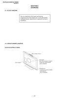
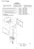
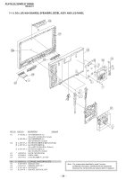
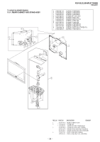
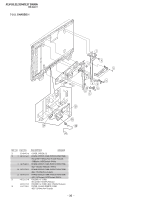
KLV-26,32,32/H/S,37 S400A RM-GA011 6-3. SCHEMATIC DIAGRAM 6-4. PRINTED WIRING BOARDS HG4 (KLV-26,32,32/H/S S400A), HG4A (KLV-37S400A), BG1, GP (KLV-26,32,32/H/S S400A), POWER UNIT (G2D) (KLV-37S400A) Boards. Board Function Note BG1 GP POWER UNIT (G2D) HG4/HG4A I/O/Audio/VCTP/DDR/HDMI/ DC-DC Converter/Tuner/Sub Croma/STBY Micro Power Supply Power Supply LED/SIRCS/Optical Sensor Due to complexity of the board, performing component level field repairs are not recommended. Complete board replacement is required if service is necessary. Therefore schematic diagrams and printed wiring boards are not included. For part number information, refer to Exploded View or Electrical Parts List section in this manual. 6-5. SEMICONDUCTOR Due to complexity of the board, performing component level field repairs are not recommended. Complete board replacement is required if service is necessary. - 25 -
-
 1
1 -
2
-
3
-
4
-
5
-
6
-
7
-
8
-
9
-
10
-
11
-
12
-
13
-
14
-
15
-
16
-
17
-
18
-
19
-
20
-
 21
21 -
 22
22 -
 23
23 -
 24
24 -
 25
25 -
 26
26 -
 27
27 -
 28
28 -
 29
29 -
 30
30 -
 31
31 -
32
-
33
-
34
-
35
-
36
-
37
-
38
-
39
-
40
-
41
-
42
-
43
-
44
-
45
-
46
-
47
-
48
-
49
-
50
-
51
-
52
-
53
-
54
-
55
-
56
-
57
-
58
-
59
-
60
-
61
-
62
-
63
-
64
-
65
-
66
-
67
-
68
-
69
-
70
-
71
-
72
-
73
-
74
-
75
-
76
-
77
-
78
-
79
-
80
-
81
 |
 |