Sony STR-DA2ES Operating Instructions - Page 62
CONTROL A1, S-LINK control, system continued
 |
View all Sony STR-DA2ES manuals
Add to My Manuals
Save this manual to your list of manuals |
Page 62 highlights
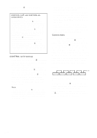
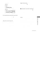
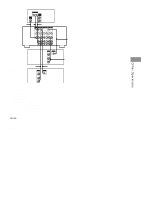
CONTROL A1 /S-LINK control system (continued) CONTROL A1 and CONTROL A1 compatibility The CONTROL A1 control system has been updated to the CONTROL A1 which is the standard system in the Sony 300 disc CD changer and other recent Sony components. Components with CONTROL A1 jacks are compatible with components with CONTROL A1 , and can be connected to each other. Basically, the majority of the functions available with the CONTROL A1 control system will be available with the CONTROL A1 control system. However, when making connections between components with CONTROL A1 jacks and components with CONTROL A1 jacks, the number of functions that can be controlled may be limited depending on the component. For detailed information, refer to the operating instructions supplied with the component(s). CONTROL A1 hookup • If you have a CONTROL A1 compatible Sony CD player, Super Audio CD player, tape deck, or MD deck Use a CONTROL A1 cord (mini jack) to connect the CONTROL A1 jack on the CD player, Super Audio CD player, tape deck, or MD deck to the CONTROL A1 jack on the receiver. See page 61 and the operating instructions supplied with your CD player, Super Audio CD player, tape deck, or MD deck for details. Note If you make CONTROL A1 connections from the receiver to an MD deck that is also connected to a computer, do not operate the receiver while using the "Sony MD Editor" software. This may cause a malfunction. • If you have a Sony CD changer with a COMMAND MODE selector If your CD changer's COMMAND MODE selector can be set to CD 1, CD 2, or CD 3, be sure to set the command mode to "CD 1" and connect the changer to the CD jacks on the receiver. If, however, you have a Sony CD changer with VIDEO OUT jacks, set the command mode to "CD 2" and connect the changer to the VIDEO 2 jacks on the receiver. Connections Connect monaural (2P) mini-plug cords in series to the CONTROL A1 jacks on the back of each component. You can connect up to 10 CONTROL A1 compatible components in any order. However, you can connect only one of each type of component (i.e., 1 CD player, 1 MD deck, 1 tape deck and 1 receiver). (You may be able to connect more than one CD player or MD deck, depending on the model. Refer to the operating instructions supplied with the respective component for details.) Example Amplifier CD MD (Receiver) player deck Tape deck Other component In the CONTROL A1 control system, the control signals flow both ways, so there is no distinction of IN and OUT jacks. If a component has more than one CONTROL A1 jack, you can use either one, or connect different components to each jack. 62GB
-
 1
1 -
2
-
3
-
4
-
5
-
6
-
7
-
8
-
9
-
10
-
11
-
12
-
13
-
14
-
15
-
16
-
17
-
18
-
19
-
20
-
21
-
22
-
23
-
24
-
25
-
26
-
27
-
28
-
29
-
30
-
31
-
32
-
33
-
34
-
35
-
36
-
37
-
38
-
39
-
40
-
41
-
42
-
43
-
44
-
45
-
46
-
47
-
48
-
49
-
50
-
51
-
52
-
53
-
54
-
55
-
56
-
 57
57 -
 58
58 -
 59
59 -
 60
60 -
 61
61 -
 62
62 -
 63
63 -
 64
64 -
 65
65 -
 66
66 -
 67
67 -
68
-
69
-
70
-
71
-
72
 |
 |