Sony STR-DA2ES Operating Instructions - Page 9
If you have a Sony components with CONTROL A1, S-LINK, Required cords
 |
View all Sony STR-DA2ES manuals
Add to My Manuals
Save this manual to your list of manuals |
Page 9 highlights
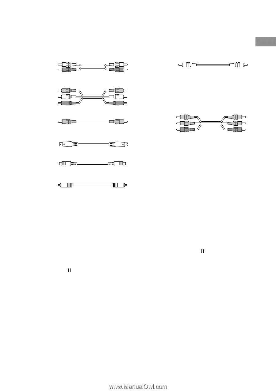
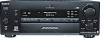
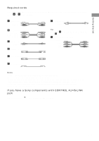
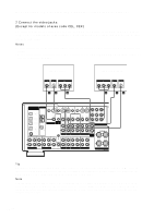
Getting Started Required cords The hookup diagrams on the subsequent pages assume the use of the following optional connection cords (A to H) (not suppiled). A Audio cord White (L) Red (R) B Audio/video cord Yellow (video) White (L/audio) Red (R/audio) C Video cord Yellow D S-video cord G Monaural audio cord Black Tip Audio cord A can be torn into two monaural audio cords G. H Component video cord (Except for models of area code CEL, CEK) Green Blue Red E Optical digital cord F Coaxial digital cord Notes • Turn off the power to all components before making any connections. • Be sure to make connections firmly to avoid hum and noise. • When connecting an audio/video cord, be sure to match the color-coded pins to the appropriate jacks on the components: yellow (video) to yellow; white (left, audio) to white; and red (right, audio) to red. • When connecting optical digital cords, insert the cord plugs straight in until they click into place. • Do not bend or tie optical digital cords. If you have a Sony components with CONTROL A1 /S-LINK jack See "CONTROL A1 /S-LINK control system" on page 61. 9GB
-
 1
1 -
2
-
3
-
 4
4 -
 5
5 -
 6
6 -
 7
7 -
 8
8 -
 9
9 -
 10
10 -
 11
11 -
 12
12 -
 13
13 -
 14
14 -
15
-
16
-
17
-
18
-
19
-
20
-
21
-
22
-
23
-
24
-
25
-
26
-
27
-
28
-
29
-
30
-
31
-
32
-
33
-
34
-
35
-
36
-
37
-
38
-
39
-
40
-
41
-
42
-
43
-
44
-
45
-
46
-
47
-
48
-
49
-
50
-
51
-
52
-
53
-
54
-
55
-
56
-
57
-
58
-
59
-
60
-
61
-
62
-
63
-
64
-
65
-
66
-
67
-
68
-
69
-
70
-
71
-
72
 |
 |