Via VB8001-16 User Manual
Via VB8001-16 - VIA Motherboard - Mini ITX Manual
 |
View all Via VB8001-16 manuals
Add to My Manuals
Save this manual to your list of manuals |
Via VB8001-16 manual content summary:
- Via VB8001-16 | User Manual - Page 1
VIA User's Manual VIA EPIA-V Mini-ITX Mainboard Version 1.2 December, 2003 P/N 99-51-012551-12 i - Via VB8001-16 | User Manual - Page 2
kind, express or implied, including without limitation implied warranties of merchantability or fitness for a particular purpose. The information provided in this manual is subject to change without notice. VIA reserves the right to alter product designs, layouts or drivers without notification. ii - Via VB8001-16 | User Manual - Page 3
with the instruction manual, may cause user's authority to operate the equipment. Notice 2 Shielded interface cables and A.C. power cord, if any, must be used in order to comply with the emission limits. VOIR LA NOTICE D'INSTALLATION AVANT DE RACCORDER AU RESEAU. VIA EPIA-M Mini-ITX Mainboard Tested - Via VB8001-16 | User Manual - Page 4
its contents. Our products are under continual improvement and we reserve the right to make changes without notice. Trademarks All trademarks used in this manual are the property of their respective owners. PS/2 and OS/2 are registered trademarks of IBM Corporation. Windows 95/98/98SE/ME/2000/NT and - Via VB8001-16 | User Manual - Page 5
NOTE 1. Always read the safety instructions carefully. 2. Keep this User's Manual for future reference. 3. Keep this equipment any of the following situations arises, get the equipment checked by a service personnel: • The power cord or plug is damaged • Liquid has penetrated into the equipment • - Via VB8001-16 | User Manual - Page 6
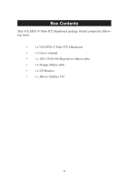
Box Contents This VIA EPIA-V Mini-ITX Mainboard package should contain the following items: • 1 x VIA EPIA-V Mini-ITX Mainboard • 1 x User's manual • 1 x ATA-33/66/100 Hard drive ribbon cable • 1 x Floppy ribbon cable • 1 x I/O Bracket • 1 x Driver Utilities CD vi - Via VB8001-16 | User Manual - Page 7
1-1 Mainboard Specifications 1-2 Mainboard Layout 1-4 Connectors Guide 1-5 Installation 2-1 CPU 2-2 The VIA C3™ E-Series Processor 2-2 The VIA Eden Processor 2-3 Memory Installation 2-4 SDRAM Module Installation Procedures 2-4 Available SDRAM Configurations 2-5 Power Supply 2-6 ATX - Via VB8001-16 | User Manual - Page 8
BIOS Features 3-8 Advanced Chipset Features 3-11 Integrated Peripherals 3-13 Power Management Setup 3-16 PNP/PCI Configurations 3-21 PC Health Status 3-23 Frequency/Voltage Control 3-24 Load Fail-Safe Defaults 3-25 Load Optimized Defaults 3-26 Set Supervisor/User - Via VB8001-16 | User Manual - Page 9
Software Setup 4-1 Driver Utilities CD Content 4-2 Getting Started 4-2 Running the Driver Utilities CD 4-2 CD Content 4-2 viii - Via VB8001-16 | User Manual - Page 10
and affordable embedded systems. Through high level of integration, mini-ITX only occupy 66% of the size of FlexATX mainboard form factor. The mainboard comes with an embedded VIA Processor, boasting ultra low power consumption and cool, quiet operation. This chapter includes the following - Via VB8001-16 | User Manual - Page 11
EBGA) • Internal L1 128KB and L2 64KB cache memory Chipset • VIA 8601A North Bridge • VT8231 South Bridge Graphics • Integrated Trident Blade • 2 x PC100/133 DIMM slots. PCI Bus IDE • Ultra DMA 33/66/100 LAN • VIA VT6103 10/100 Base-T Ethernet PHY USB • 2 USB ports • 1 onboard USB pin header for up - Via VB8001-16 | User Manual - Page 12
• 1 RJ45 LAN port • 1 Serial port • 2 USB 1.1 ports • 1 VGA port • 1 RCA port (S/PDIF or TV out) • 1 S-Video port Power • Supports ATX type power supply Onboard Floppy • 1 FDD connector BIOS • Award BIOS • 2/4Mbit flash memory Form Factor • Mini-ITX (4 layers) • 17 cm x 17 cm 1-3 Specifications - Via VB8001-16 | User Manual - Page 13
PS / 2 Keyboard Mouse PS2 Connector J6 South Bridge VT8231 J5 FIR Module Connector North Bridge VT8601A Processor EBGA Clock Generator DIMM 1 J13 Host Frequency Select BIOS ROM FDD IDE 1 DIMM 2 ATX Power Connector VIA EPIA-V Mini-ITX Mainboard 1-4 - Via VB8001-16 | User Manual - Page 14
Guide Specifications Component Fan 1, Fan 2 DIMM1, DIMM2 ATX Power Slot PCI IRQ Function Fan power connectors DIMM slot Connecting ATX power supply Mouse connector Keyboard connector 13 See p. 2-13 See p. 2-14 See p. 2-14 See p. 2-15 See p. 2-16 See p. 2-17 See p. 2-17 See p. 2-18 See p. 2-19 1-5 - Via VB8001-16 | User Manual - Page 15
handling computer components. The components can be damaged by static electricity. This chapter contains the following topics: Central Processing Unit (CPU) Memory Installation Power Supply Back Panel Connectors Jumpers Slots PCI Interrupt Request Routing 2-2 2-4 2-6 2-7 2-10 2-15 2-18 2-19 2-1 - Via VB8001-16 | User Manual - Page 16
EPIA-V Mini-ITX Mainboard includes an embedded VIA Eden Processor or VIA C3™ E-Series Processor. Two fan connectors (Fan 1 & Fan 2) are provided on the mainboard, allowing for the connection of a CPU fan and an additional system case fan. The VIA C3™ E-Series Processor With low power consumption - Via VB8001-16 | User Manual - Page 17
Providing ultra-low power consumption and advanced thermal dissipation properties, the VIA Eden Processor features a fanless design. The VIA Eden Processor requires only a heatsink, as shown below. CPU Heatsink Overclocking This motherboard is not designed to support overclocking. Any attempt - Via VB8001-16 | User Manual - Page 18
Chapter 2 Memory Installation The VIA EPIA-V Mini-ITX Mainboard provides two 168-pin DIMM slots for PC 100/133 SDRAM memory modules. To operate properly, at least one module must be installed. DIMM 1 & DIMM 2 - Via VB8001-16 | User Manual - Page 19
SDRAM Configurations Refer to the table below for available SDRAM configurations on the VIA EPIA-V Mini-ITX Mainboard. Socket Memory Module Total M emory DIMM 1 DIMM 2 32MB, 64MB, 128MB, 32MB~512MB 256MB, 512MB 32MB, 64MB, 128MB, 32MB~512MB 256MB, 512MB Maximum System Memory Supported 1GB 2-5 - Via VB8001-16 | User Manual - Page 20
2 Power Supply The VIA EPIA-V Mini-ITX Mainboard requires an ATX power supply to be connected. Before inserting the power supply connector, always make sure that all components are installed correctly to ensure that no damage will be caused. ATX 20-Pin Power Connector To connect the ATX power supply - Via VB8001-16 | User Manual - Page 21
Hardware Setup Back Panel The back panel of the VIA EPIA-V Mini-ITX Mainboard contains the following connectors: PS/2 Mouse LPT Connector RJ-45 Port COM Port PS/2 Keyboard S-Video Port USB Ports CRT Connector RCA Video or S / P DIF - Via VB8001-16 | User Manual - Page 22
LPT1 The mainboard provides a 25-pin female connector for LPT (parallel port). A parallel port is a standard printer port that supports Enhanced Parallel End 13 SELECT Select 14 AUTO FEED# Automatic Feed 15 ERR# Error 16 INIT# Initialize Printer 17 SLIN# Select In 18 GND Ground 19 GND - Via VB8001-16 | User Manual - Page 23
Hardware Setup Serial Port Connectors: COM 1 The mainboard offers one 9-pin male Serial Port connector (COM 1) . You can attach a serial mouse or other serial devices directly to this port. 1 2 3 4 5 6 7 8 9 9-Pin Male DIN Connectors - Via VB8001-16 | User Manual - Page 24
Chapter 2 Connectors The VIA EPIA-V Mini-ITX Mainboard provides the following connectors: Hard Disk Connectors: IDE1 The mainboard has a 32-bit Enhanced PCI IDE and Ultra DMA 33/ its jumper. Refer to the hard disk documentation supplied by hard disk vendors for jumper setting instructions. 2-10 - Via VB8001-16 | User Manual - Page 25
Hardware Setup Front Panel Connector (J3) The J3 front panel connectors allow you to connect the Power Switch, Reset Switch, Power LED and HDD LED to the system case. 1 HDD LED Power Switch Reset 11 2 Power LED 12 CD-ROM Line In Connector (J7) The J7 internal CD-ROM Line In Connector allows you - Via VB8001-16 | User Manual - Page 26
Connector (J5) The FIR Module Connector (J5) allows you to connect a Fast Infrared standard module. You must configure the setting through the BIOS setup to activate the IR function. Pin Definition PIN SIGNAL 1 1 +3V 2 IRRX 3 IRRX2 4 GND 5 IRTX PS2 Connector (J6) When this connector - Via VB8001-16 | User Manual - Page 27
Setup Wake On Modem Connector (J8) This connector (J8) allows you to connect to a modem with the Wake On Modem function. The connector will power up the system when a signal is received through the modem. 1 +5V_SB GND WOM USB Port 2&3 Connector (F_USB) This connector allows you to connect an - Via VB8001-16 | User Manual - Page 28
(J12) The Video In Connector allows you to connect an external video source. 15 1 16 2 PIN SIGNAL PIN 1 GND 2 3 CVD7 4 5 CVD6 6 7 CVHS 8 9 CVD1 10 11 CVVS 12 13 A_D30 14 15 -GNT2 16 SIGNAL CVD0 CVD4 CVD5 CVD2 CVD3 CVCLK -REQ2 Floppy Disk Drive Connector: FDD The standard - Via VB8001-16 | User Manual - Page 29
functions. This section explains how to change settings for your mainboard's functions through the use of the jumpers. Clear CMOS Jumper: CLEAR_CMOS (J10) The onboard CMOS RAM stores system configuration data and has an onboard battery power supply. The long-life battery has a lifetime of at least - Via VB8001-16 | User Manual - Page 30
be used to select the host frequency bus speed of the mainboard. The three available options are 66MHz, 100MHz and 133MHz. J13 Host Frequency Select Overclocking WARNING! This motherboard is not designed to support overclocking. Any attempt to operate beyond product specifications is not recommended - Via VB8001-16 | User Manual - Page 31
disables the Auto Reboot Function Setting. When enabled, the system will automatically reboot in the event it of sudden power outage. 1 1-2: Disable 2-3: Enable RCA Video or S/PDIF Select (J11) Users can select either RCA Video or S/PDIF as the enabled function on the dual-purpose port. For TV-out - Via VB8001-16 | User Manual - Page 32
Slots PCI Slot The PCI slot allows you to insert PCI expansion card. When adding or removing expansion cards, make sure that you unplug the power supply first. Meanwhile, read the documentation for the expansion card to make any necessary hardware or software settings for the expansion card, such as - Via VB8001-16 | User Manual - Page 33
Hardware Setup PCI Interrupt Request Routing PCI Interrupt Request Routing The IRQ (Interrupt ReQuest) is the mechanism for devices to request services from the microprocessor. The "PCI & LAN" IRQ pins are typically connected to the PCI bus INT A# ~ INT D# pins as follows: PCI Slot 1 LAN Order 1 - Via VB8001-16 | User Manual - Page 34
Chipset Features Integrated Peripherals Power Management Setup PNP/PCI Configurations PC Health Status Frequency/Voltage Control Load Fail-Safe Defaults Load Optimized Defaults Set Supervisor/User Password Save & Exit Setup Exit Without Saving 3-2 3-2 3-3 3-4 3-6 3-8 3-11 3-13 3-16 3-21 3-23 3-24 - Via VB8001-16 | User Manual - Page 35
Chapter 3 Entering Setup Power on the computer and press DEL straight away to enter the BIOS setup menu. If you missed the BIOS setup entry point, you may restart the system and try again. Control Keys Enter> Move to the - Via VB8001-16 | User Manual - Page 36
-menu. To return from the sub-menu press . IDE Primary Master IDE Primary Slave IDE Secondary Master IDE Secondary Slave General Help The BIOS setup program provides a General Help screen. You can call up this screen from any menu/sub-menu by pressing . The help screen displays the - Via VB8001-16 | User Manual - Page 37
Standard CMOS Features Use this menu to set basic system configurations. Advanced BIOS Features Use this menu to set the advanced features available on your to set onboard peripherals features. Power Management Setup Use this menu to set onboard power management functions. PnP/PCI Configurations - Via VB8001-16 | User Manual - Page 38
Optimized Defaults Use this menu to load BIOS default settings for optimal and high performance system operations. Set Supervisor Password Use this menu to set supervisor password. Set User Password Use this menu to set user password. Save & Exit Setup Save BIOS setting changes and exit setup. Exit - Via VB8001-16 | User Manual - Page 39
Chapter 3 Standard CMOS Features Use the arrow keys to highlight the item and use the or keys to select the value you desire for each item. Date The date format is . Day - day of the week, for example Friday. Read-only. Month - the month from Jan to Dec. Date - - Via VB8001-16 | User Manual - Page 40
BIOS Setup IDE Primary Master/Slave Press to enter the sub-menu and work properly if you enter improper information for this category. Select Auto whenever possible. If you select Manual, make sure the information provided is from your hard disk vendor or system manufacturer. IDE Primary - Via VB8001-16 | User Manual - Page 41
. Processor Number Feature Set the CPU internal serial number. Settings: Enabled and Disabled. Quick Power On Self Test Shorten Power On Self Test (POST) cycle and enable shorter bootup time. Allow BIOS to skip some check items during POST. Settings: Enabled and Disabled. First/Second/Third Boot - Via VB8001-16 | User Manual - Page 42
Enabled and Disabled. Boot Up Floppy Seek Set floppy seek during POST, BIOS will determine whether the floppy is 40 or 80 tracks. Settings: Enabled and Disabled. Boot Up NumLock Status Set the NumLock status when the system is powered on. "On" will turn key pad into number keys, and "Off" will - Via VB8001-16 | User Manual - Page 43
try to run Setup. System A password prompt appears every time when the computer is powered on or when end users try to run Setup. Display Full Screen logo Show full screen logo during BIOS bootup process. Settings: Enabled and Disabled. Show Summary Information Show summary information during - Via VB8001-16 | User Manual - Page 44
BIOS Setup Advanced Chipset Features The Advanced Chipset Features menu is used for optimizing the chipset functions. Note: Change these settings only if you are familiar - Via VB8001-16 | User Manual - Page 45
Chapter 3 P2C/C2P Concurrency Fast R-W Turn Around PCI Dynamic Bursting PCI#2 Access #1 Retry The settings are Enabled and Disabled. The settings are Enabled and Disabled. The settings are Enabled and Disabled. The settings are Enabled and Disabled. CPU to PCI POST Write When Enabled, CPU can - Via VB8001-16 | User Manual - Page 46
Integrated Peripherals BIOS Setup Onboard IDE Channel The integrated peripheral controller contains an IDE interface. Choose Enabled to activate the channel. Settings: Disabled, Enabled. IDE Prefetch Mode This - Via VB8001-16 | User Manual - Page 47
Audio Auto allows the mainboard to detect whether an audio device is used. If the device is detected, the onboard VIA AC'97 (Audio Codec VIA-3043 OnChip LAN Decide whether to invoke the boot ROM of VIA-3043 onchip LAN. Settings: Enabled and Disabled. USB Keyboard Support Enable USB Keyboard Support - Via VB8001-16 | User Manual - Page 48
BIOS Setup VIA SuperIO Device Press to enter the sub-menu and the following Set the base I/O port address and IRQ for the onboard serial port A/serial port B. Selecting Auto allows BIOS to automatically determine the correct base I/O port address. Settings: Disabled, 3F8/IRQ4, 2F8/IRQ3, 3E8/ - Via VB8001-16 | User Manual - Page 49
save energy while operating in a manner consistent with your own style of computer use. ACPI Function Activate the ACPI (Advanced Configuration and Power Management Interface) Function. If your operating system is ACPI-aware (i.e. Windows 98/98SE/ME/2000/XP) select Enabled. Settings: Enabled and - Via VB8001-16 | User Manual - Page 50
no system context (CPU or chipset) is lost and hardware maintains all system context. S3/STR - S3/Suspend To RAM (STR) is a power-down state. In this state, power is supplied only to essential components such as main memory and wakeup-capable devices. The system context is saved to main memory, and - Via VB8001-16 | User Manual - Page 51
management unit should monitor hard disks and floppy drives activties. Settings: Off and On. PCI Master Event Decide whether or not the power management unit should monitor PCI master activties. Settings: Off and On. PS2KB Wakeup Select When Select Password, Please press ENTER key to change Password - Via VB8001-16 | User Manual - Page 52
BIOS Setup PS2KB Wakeup from suspend Select which "Hot-Key" is used to wake-up the system from power saving mode. Settings: Disabled, Ctrl+F1, Ctrl+F2, Ctrl+F3, Ctrl+F4, Ctrl+F5, Ctrl+F6, Ctrl+F7, Ctrl+F8, Ctrl+F9, Ctrl+F10, Ctrl+F11, Ctrl+F12, Power not a PCI card can power up the system or resume - Via VB8001-16 | User Manual - Page 53
the following screen appears: Primary INTR Selecting ON will cause the system to wake up from power saving modes if activity is detected from any enabled IRQ channels. Settings: OFF and ON. IRQ3~IRQ15 is ready, the system will interrupt itself and perform the service required by the IO device. 3-20 - Via VB8001-16 | User Manual - Page 54
experienced users should make any changes to the default settings. PNP OS Installed When set to Yes, BIOS will Windows® 95 or 98/98SE. When set to No, BIOS will initialize all the PnP cards. Set to Yes the operating . Resource Controlled By The BIOS can automatically configure all the boot and Plug - Via VB8001-16 | User Manual - Page 55
Chapter 3 IRQ Resources The items are adjustable only when Resources Controlled By is set to Manual. Press and you will enter the sub-menu of the items. IRQ Resources list IRQ 3/4/5/7/9/10/11/12/14/15 for users to set each IRQ a type depending on the type of device using the IRQ - Via VB8001-16 | User Manual - Page 56
BIOS Setup PC Health Status This section shows the status of your CPU, fan, warning for overall system status. Current CPU Temp, CPU Fan Speed, System - Via VB8001-16 | User Manual - Page 57
Frequency/Voltage Control DRAM Clock The chipset supports synchronous and asynchronous mode between host clock and module. Selecting Yes makes SDRAM Cycle Length and Bank Interleave automatically determined by BIOS according to the configurations on the SPD. Settings: Disabled and Enabled. SDRAM - Via VB8001-16 | User Manual - Page 58
Load Fail-Safe Defaults This option on the main menu allows users to restore all the BIOS settings to the default Fail Safe values. These values are set by the mainboard manufacturer to provide the most stable system. When you select Load-Fail Safe Defaults, a message as below appears: Pressing - Via VB8001-16 | User Manual - Page 59
This option on the main menu allows users to restore all the BIOS settings to the default Optimized values. The Optimized Defaults are the default values also set by the mainboard manufacturer for both optimized and stable performance of the mainboard. When you select Load Optimized Defaults - Via VB8001-16 | User Manual - Page 60
BIOS Setup Set Supervisor/User Password When you select this function, a message as below will . The setting to determine when the password prompt is required is the Security Option of the Advanced BIOS Features menu. If the Security Option is set to System, the password is required both at boot - Via VB8001-16 | User Manual - Page 61
Chapter 3 About Supervisor Password & User Password: Supervisor password : Can enter and change the settings of the setup menus. User password: Can only enter but do not have the right to change the settings of the setup menus. 3-28 - Via VB8001-16 | User Manual - Page 62
BIOS Setup Save & Exit Setup When you want to quit the Setup menu, you can select this option to save the changes and quit. A message as below will appear on the screen: Typing "Y" will allow you to quit the Setup Utility and save the user setup changes to RTC CMOS. Typing "N" will return - Via VB8001-16 | User Manual - Page 63
Chapter 3 Exit Without Saving When you want to quit the Setup menu, you can select this option to abandon the changes. A message as below will appear on the screen: Typing "Y" will allow you to quit the Setup Utility without saving any changes to RTC CMOS. Typing "N" will return to the Setup Utility - Via VB8001-16 | User Manual - Page 64
gives you brief descriptions of each mainboard drivers and applications. It consists of the following topic: Driver Utilities CD Content 4-2 Note: You must install VIA chipset drivers first before installing other drivers such as audio or VGA drivers. The applications will only function correctly - Via VB8001-16 | User Manual - Page 65
Started The VIA EPIA-V mainboard includes a Driver Utilities CD which contains driver utilities and software to enhance the performance of the mainboard. Please check . If the CD does not run automatically, you can run the CD manually by typing "D:\Setup.exe" at Start\Run. (Please note that D: - Via VB8001-16 | User Manual - Page 66
's PCI IRQ routing sequence) and VIA INF Driver (enables the VIA Power Management function). - VIA Graphics Driver: Enhance the onboard VIA graphic chip. - VIA Audio Driver: Enhance the onboard VIA audio chip. - VIA LAN Driver: Enhance the onboard VIA LAN chip. - VIA FIR Driver: Support for FIR. 4-3
-
 1
1 -
 2
2 -
 3
3 -
 4
4 -
 5
5 -
 6
6 -
 7
7 -
8
-
9
-
10
-
11
-
12
-
13
-
14
-
15
-
16
-
17
-
18
-
19
-
20
-
21
-
22
-
23
-
24
-
25
-
26
-
27
-
28
-
29
-
30
-
31
-
32
-
33
-
34
-
35
-
36
-
37
-
38
-
39
-
40
-
41
-
42
-
43
-
44
-
45
-
46
-
47
-
48
-
49
-
50
-
51
-
52
-
53
-
54
-
55
-
56
-
57
-
58
-
59
-
60
-
61
-
62
-
63
-
64
-
65
-
66
 |
 |

i
Version 1.
2
December
, 2003
VIA
User’s Manual
VIA EPIA-V
Mini-ITX Mainboard
P/N 99-51-012551
-12