Via VB8001-16 User Manual - Page 7

Contents - power supply

Page 7 highlights

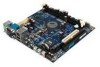
Contents Specifications 1-1 Mainboard Specifications 1-2 Mainboard Layout 1-4 Connectors Guide 1-5 Installation 2-1 CPU 2-2 The VIA C3™ E-Series Processor 2-2 The VIA Eden Processor 2-3 Memory Installation 2-4 SDRAM Module Installation Procedures 2-4 Available SDRAM Configurations 2-5 Power Supply 2-6 ATX 20-Pin Power Connector: ATXPWR 2-6 Back Panel 2-7 Mouse Connector: JMS1 2-7 Keyboard Connector: JKB1 2-7 USB Port Connectors 2-8 RJ-45 NIC Port 2-8 Parallel Port Connector: LPT1 2-8 Serial Port Connector: COM 1 2-9 S-Video Port 2-9 Audio Port Connectors 2-9 RCA Video or S/PDIF Port 2-9 VGA Out 2-9 Connectors 2-10 Hard Disk Connectors: IDE1 2-10 Front Panel Connector (J3 2-11 CD-ROM Line In Connector (J7 2-11 FIR Module Connector (J5 2-12 PS2 Connector (J6 2-12 Wake On Modem Connector (J8 2-13 USB Port 2&3 Connector (F_USB 2-13 vi

  • 1
  • 2
  • 3
  • 4
  • 5
  • 6
  • 7
  • 8
  • 9
  • 10
  • 11
  • 12
  • 13
  • 14
  • 15
  • 16
  • 17
  • 18
  • 19
  • 20
  • 21
  • 22
  • 23
  • 24
  • 25
  • 26
  • 27
  • 28
  • 29
  • 30
  • 31
  • 32
  • 33
  • 34
  • 35
  • 36
  • 37
  • 38
  • 39
  • 40
  • 41
  • 42
  • 43
  • 44
  • 45
  • 46
  • 47
  • 48
  • 49
  • 50
  • 51
  • 52
  • 53
  • 54
  • 55
  • 56
  • 57
  • 58
  • 59
  • 60
  • 61
  • 62
  • 63
  • 64
  • 65
  • 66

vi
Contents
Specifications
.........................................................
1-1
Mainboard Specifications
................................................
1-2
Mainboard Layout
............................................................
1-4
Connectors Guide
............................................................
1-5
Installation
.............................................................
2-1
CPU
.................................................................................
2-2
The VIA C3™ E-Series Processor
...................................
2-2
The VIA Eden Processor
..................................................
2-3
Memory Installation
.........................................................
2-4
SDRAM Module Installation Procedures
..........................
2-4
Available SDRAM Configurations
.....................................
2-5
Power Supply
..................................................................
2-6
ATX 20-Pin Power Connector: ATXPWR
.......................
2-6
Back Panel
.......................................................................
2-7
Mouse Connector: JMS1
..................................................
2-7
Keyboard Connector: JKB1
..............................................
2-7
USB Port Connectors
.......................................................
2-8
RJ-45 NIC Port
.................................................................
2-8
Parallel Port Connector: LPT1
.........................................
2-8
Serial Port Connector: COM 1
..........................................
2-9
S-Video Port
.....................................................................
2-9
Audio Port Connectors
.....................................................
2-9
RCA Video or S/PDIF Port
..............................................
2-9
VGA Out
...........................................................................
2-9
Connectors
.....................................................................
2-10
Hard Disk Connectors: IDE1
..........................................
2-10
Front Panel Connector (J3)
.............................................
2-11
CD-ROM Line In Connector (J7)
...................................
2-11
FIR Module Connector (J5)
............................................
2-12
PS2 Connector (J6)
........................................................
2-12
Wake On Modem Connector (J8)
...................................
2-13
USB Port 2&3 Connector (F_USB)
...............................
2-13