Via VB8001-16 User Manual - Page 18
Memory Installation - epia
 |
View all Via VB8001-16 manuals
Add to My Manuals
Save this manual to your list of manuals |
Page 18 highlights
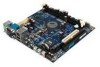
Chapter 2 Memory Installation The VIA EPIA-V Mini-ITX Mainboard provides two 168-pin DIMM slots for PC 100/133 SDRAM memory modules. To operate properly, at least one module must be installed. DIMM 1 & DIMM 2 SDRAM Module Installation Procedures 1.) Push the white retaining latches at either end of the DIMM slot outwards. 2.) Align the SDRAM module with the corresponding notches on the DIMM slot. The modules will only fit if placed in the correct position. 2.) With both hands, press the SDRAM module down into the DIMM slot so that the white retaining latches rotate up and secure the module in place (see picture below). 2-4
-
 1
1 -
2
-
3
-
4
-
5
-
6
-
7
-
8
-
9
-
10
-
11
-
12
-
 13
13 -
 14
14 -
 15
15 -
 16
16 -
 17
17 -
 18
18 -
 19
19 -
 20
20 -
 21
21 -
 22
22 -
 23
23 -
24
-
25
-
26
-
27
-
28
-
29
-
30
-
31
-
32
-
33
-
34
-
35
-
36
-
37
-
38
-
39
-
40
-
41
-
42
-
43
-
44
-
45
-
46
-
47
-
48
-
49
-
50
-
51
-
52
-
53
-
54
-
55
-
56
-
57
-
58
-
59
-
60
-
61
-
62
-
63
-
64
-
65
-
66
 |
 |

Chapter 2
2-4
The VIA EPIA-V Mini-ITX Mainboard provides two 168-pin DIMM slots
for PC 100/133 SDRAM memory modules. To operate properly, at least one
module must be installed.
Memory Installation
DIMM 1 & DIMM 2
SDRAM Module Installation Procedures
1.) Push the white retaining latches at either end of the DIMM slot outwards.
2.) Align the SDRAM module with the corresponding notches on the DIMM
slot. The modules will only fit if placed in the correct position.
2.) With both hands, press the SDRAM module down into the DIMM slot so
that the white retaining latches rotate up and secure the module in place (see
picture below).