ViewSonic VA1912W Service Manual
ViewSonic VA1912W - 19" LCD Monitor Manual
 |
UPC - 766907167313
View all ViewSonic VA1912W manuals
Add to My Manuals
Save this manual to your list of manuals |
ViewSonic VA1912W manual content summary:
- ViewSonic VA1912W | Service Manual - Page 1
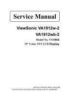
Service Manual ViewSonic VA1912w-2 VA1912wb-2 Model No. VS10866 19" Color TFT LCD Display (VA1912w-2_VA1912wb-2_SM Rev. 1b Aug. 2006) ViewSonic 381 Brea Canyon Road, Walnut, California 91789 USA - (800) 888-8583 - ViewSonic VA1912W | Service Manual - Page 2
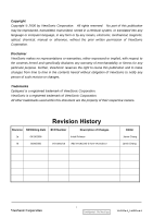
are the property of their respective owners. Revision History Revision SM Editing Date ECR Number Description of Changes 1a 04/14/2006 Initial Release 1b 8/09/2006 VS-E060210 Add VA1912wb-2 from VA1912w-2 Editor Jamie Chang Jamie Chang ViewSonic Corporation i Confidential - Do Not Copy - ViewSonic VA1912W | Service Manual - Page 3
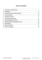
Description 10 4. Circuit Description 16 5. Adjustment Procedure 17 6. Troubleshooting Flow Chart 37 7. Recommended Spare Parts List 45 8. Exploded Diagram and Exploded Parts List 50 9. Block Diagram 52 10. Schematic Diagrams 53 11. PCB Layout Diagrams 60 ViewSonic Corporation ii - ViewSonic VA1912W | Service Manual - Page 4
such areas as the associated transformer circuits. 4. LCD Module Handling Precautions 4.1 Handling Precautions (1) Since front polarizer is easily damaged, pay attention not to scratch it. (2) Be sure to turn off power supply when connecting or disconnecting input connector. (3) Wipe off water drops - ViewSonic VA1912W | Service Manual - Page 5
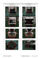
the monitor with cushion Take out the monitor by grasping the LCD panel. That may cause " MURA". Place the monitor on a clean & soft foam pad . Place the monitor on foreign objects . That could scratch the surface of panel ViewSonic Corporation 2 Confidential - Do Not Copy VA1912w-2_VA1912wb - ViewSonic VA1912W | Service Manual - Page 6
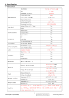
2. Specification 2.1 INSTRUCTION TFTLCD PANEL Input Signal Sync Compatibility Compatibility Power Voltage Power Consumption Audio Ergonomics OSD Control FEATURES Size Luminance (Typ, cd/㎡) Contrast Ratio (Typ) Colors ( 6 bit + 2 bit FRC) Response Time (Typ) Viewing Angle (H/V) Recommend resolution - ViewSonic VA1912W | Service Manual - Page 7
Signal Sync Signals DDC 2B Sync Compatibility Video Compatibility Resolution Compatibility Exclusions 1440 x 900 @ 60Hz Full Size Factory Default: Contrast = 70%, Brightness = 100% DB-15 (Analog), refer the appendix A N/A Defaults to the first detected input Equal to twice the weight of the monitor - ViewSonic VA1912W | Service Manual - Page 8
) with no damage Shall be able to function properly, without reset or visible screen artifacts, when ½ cycle of AC power is randomly missing at nominal input The power supply shall not produce audible noise that would be detectable by the user. Audible shall defined to be in compliance with ISO 7779 - ViewSonic VA1912W | Service Manual - Page 9
2.5 ELECTRICAL REQUIREMENT Horizontal / Vertical Frequency Horizontal Frequency Vertical Refresh Rate Maximum Pixel Clock Sync Polarity 30 - 82 kHz 50 - 85* Hz. 135 MHz (EDID file is 140MHz) Independent of sync polarity. Timing Table Item Timing 1 - ViewSonic VA1912W | Service Manual - Page 10
when input 720x400 or 640x400 mode [1 White Balance. (Not shown on user's guide) [1] + [▼] Power Lock [1] + [▲] [;X] OSD Lock Audio Mute on /off Remark : All the short cuts function are only available while OSD off ViewSonic Corporation 7 Confidential - Do Not Copy VA1912w-2_VA1912wb - ViewSonic VA1912W | Service Manual - Page 11
Language, Power Lock, User Color Settings or Input Priority Resolution Notice Actions 1. Resolution Notice OSD should show on screen after changing to reset by Memory Recall function (Should not reset by power off, power unplug and others) ViewSonic Corporation 8 Confidential - Do Not Copy VA1912w - ViewSonic VA1912W | Service Manual - Page 12
save new settings when it is turned off by the user or when it times out. There shall not be a separate save 2.7 AUDIO INTERFACE (SPEAKER SPECIFICATION) Line input connection 3.5 mm stereo jack Line input signal 1 Vrms Line input impedance Maximum power output (Electric) 20k ohms 1.5W / CH - ViewSonic VA1912W | Service Manual - Page 13
Screen Image Use the buttons on the front control panel to display and adjust the OSD controls which display on the screen. The OSD controls are explained at the top of the next page and are defined in "Main Menu Controls" on page 10. ViewSonic Corporation 10 Confidential - Do Not Copy VA1912w - ViewSonic VA1912W | Service Manual - Page 14
1440 x 900 @ 60Hz video signal to the LCD display. (Look for instructions on "changing the refresh rate" in the graphics card's user guide.) • If necessary, make small adjustments using H. POSITION and V. POSITION until the screen image is completely visible. (The black border around the edge of the - ViewSonic VA1912W | Service Manual - Page 15
-Adds blue and green to the screen image for a darker color. User Color Individual adjustments for red (R), green (G), and blue (B). 1. To select color (R, G or B) press button [2]. 2. To adjust selected color, press and . . Important: If you select RECALL from the Main Menu when the product is set - ViewSonic VA1912W | Service Manual - Page 16
's user guide for instructions on changing the resolution and refresh rate (vertical frequency). NOTE: VESA 1440 x 900 @ 60Hz (recommended) means that the resolution is 1440 x 900 and the refresh rate is 60 Hertz. Manual Image Adjust Sub-menu H. Size (Horizontal Size) adjusts the width of the screen - ViewSonic VA1912W | Service Manual - Page 17
Adjust first. Sharpness adjusts the clarity and focus of the screen image. Setup Menu displays the menu shown below: Language Select allows the user to choose the language used in the menus and control screens. Resolution Notice allows the user to enable or disable this notice. If you enable the - ViewSonic VA1912W | Service Manual - Page 18
allows the user to turn the OSD background On or Off. Memory Recall returns the adjustments back to factory settings if the display is operating in a factory Preset Timing Mode listed in the Specifications of this manual. ViewSonic Corporation 15 Confidential - Do Not Copy VA1912w-2_VA1912wb-2 - ViewSonic VA1912W | Service Manual - Page 19
4. Circuit Description The TSUM17AK is total solution graphics processing IC for LCD monitors with panel resolutions up to SXGA. It is configured with a high-speed integrated triple-ADC/PLL,, a high quality display processing engine, and an integrated output display interface that can support RSDS - ViewSonic VA1912W | Service Manual - Page 20
Auto Adjust is aimed to offer a best screen quality by built-in ASIC. For optimum screen quality, the user has to adjust each function manually. A.Turn the computer and LCD monitor on. B. Press the 'Auto' button on monitor keypad to Auto Adjust. C. The LCD monitor will start the Auto Adjust process - ViewSonic VA1912W | Service Manual - Page 21
10. Black Box Test Signal: 1280*1024@60Hz Test Pattern: Window standard pattern Inspection Item: Bright Dot, Line Defect & Power 11. RED Test Signal: 1280*1024@60Hz Test Pattern: Full Screen Red Inspection Item: Bright Dot, Partial & Line Defect 12. Green Test Signal: 1280*1024@60Hz Test Pattern: - ViewSonic VA1912W | Service Manual - Page 22
Figure 1 Figure 3 Figure 5 Figure 2 Figure 4 Figure 6 Figure 7 ViewSonic Corporation Figure 8 19 Confidential - Do Not Copy VA1912w-2_VA1912wb-2 - ViewSonic VA1912W | Service Manual - Page 23
PC and Print Port of fixture(and EDID burn in the same fixture) to connect VGA Cable between D-sub of fixture and D-sub of AD Board of monitor,the monitor must be turned on the power。 Step 2 : Open ISP Tool ViewSonic Corporation 20 Confidential - Do Not Copy VA1912w-2_VA1912wb-2 - ViewSonic VA1912W | Service Manual - Page 24
figure is displayed "Device Type is Pm25LV512" then press "確定"。 Step 4: Press "Read" then enter as below figure,then press to down load the program of BIOS (*.bin)。 If down load BIOS that is successful as below figure then press"確定"。 ViewSonic Corporation 21 Confidential - Do Not Copy VA1912w - ViewSonic VA1912W | Service Manual - Page 25
figure is displayed "0x1626" then press "Run" to execute the BIOS procedure。 The BIOS procedure is displayed the message "Verify OK" that the BIOS procedure is successful。 Step 6 : Press "Dis Con" then leave the mode of ISP。 ViewSonic Corporation 22 Confidential - Do Not Copy VA1912w-2_VA1912wb-2 - ViewSonic VA1912W | Service Manual - Page 26
Step 7: When select "ReConnect" and press "Run" then repeat to connect the mode of ISP into next the action of BIOS procedure ViewSonic Corporation 23 Confidential - Do Not Copy VA1912w-2_VA1912wb-2 - ViewSonic VA1912W | Service Manual - Page 27
Figure 2 1.3 Put the cushions on the monitor. (Figure 3) 1.4 Place the monitor into the carton and then put all the accessories into the carton. As last, close the carton and seal it with tape. (Figure 4) Figure 3 ViewSonic Corporation Figure 4 24 Confidential - Do Not Copy VA1912w-2_VA1912wb-2 - ViewSonic VA1912W | Service Manual - Page 28
Monitor Assembly and Disassembly 1 Separate Stand Assy 1.1 Remove Stand Cover Step 1 : Remove the Seat Assy Step 2 : Remove the Stand Cover. Step 3 : Loose and remove 4 screws Step4 : Remove the Stand Assy Step 5 : Completed. ViewSonic Corporation 25 Confidential - Do Not Copy VA1912w- - ViewSonic VA1912W | Service Manual - Page 29
Rear Cover apart. Step 1 : Loose and remove 2 screws. Step 2 : Separate Bezel hooks to take Bezel and Rear Cover apart. Step 3 : Remove Rear Cover. Step 4 : Completed. ViewSonic Corporation 26 Confidential - Do Not Copy VA1912w-2_VA1912wb-2 - ViewSonic VA1912W | Service Manual - Page 30
3 Remove Power Board and AD Board 3.1 Remove Metal Cover Step 1 : Remove FFC from OSD Board. Step 2 : Loose and remove 4 screws. Step 3 : Lift up LCD module and remove bezel. Step 4 : Remove 2 pieces of Backlight wires. Step 5 : Remove 2 pieces of Backlight wires. ViewSonic Corporation 27 - ViewSonic VA1912W | Service Manual - Page 31
Step 6 : Loose and remove 2 screws. Step 7 : Loose and remove 2 screws. Step 8 : Loose and remove 4 screws. Step 9 : Remove the PCBA Cover ViewSonic Corporation 28 Confidential - Do Not Copy VA1912w-2_VA1912wb-2 - ViewSonic VA1912W | Service Manual - Page 32
3.2 Remove Power Board and AD Board Step 1 : Loose and remove 4 screws. Step 2 : Remove Lips Board Step 3 : Remove 2 pieces of FFCs. Step 4 : Remove the FFC. Step 5 : Loose and remove 4 screws. ViewSonic Corporation 29 Confidential - Do Not Copy VA1912w-2_VA1912wb-2 - ViewSonic VA1912W | Service Manual - Page 33
6 : Remove AD PCBA. Step7 : Completed. 4 Change New AD Board and Power Board Step 1 : Place new AD Board. And fasten 4 fixed screws. Step 2 : Fasten 4 fixed screws. Step 3 : Insert FFC. Step 4 : Insert 2 pieces of FFCs . ViewSonic Corporation 30 Confidential - Do Not Copy VA1912w-2_VA1912wb-2 - ViewSonic VA1912W | Service Manual - Page 34
Step 5 : Insert new Lips Board. Step 6 : Fasten 4 fixed screws. Step 7 :Completed. ViewSonic Corporation 31 Confidential - Do Not Copy VA1912w-2_VA1912wb-2 - ViewSonic VA1912W | Service Manual - Page 35
5. Remove OSD Board Step 1 : Separate both Audio Cable. Step 2 : Take OSD Board apart. Step 3: Completed. ViewSonic Corporation 32 Confidential - Do Not Copy VA1912w-2_VA1912wb-2 - ViewSonic VA1912W | Service Manual - Page 36
6.Change New OSD Board Step 1 : Place New OSD Board. Step 2 : Insert Audio cable to connectors of New OSD Board. Step 3: Completed. 7. Add Cover to AD PCB Heatsink Step 1 : Join the PCB Cover. Step 2 : Fasten 4 fixed screws. ViewSonic Corporation 33 Confidential - Do Not Copy VA1912w-2_VA1912wb - ViewSonic VA1912W | Service Manual - Page 37
Step 3 : Fasten 2 fixed screws Step 4 : Fasten 2 fixed screws. Step 5 : Insert 2 pieces of Backlight wires. Step 6 : Insert 2 pieces of Backlight. wires. Step 7 : Join LCD module and remove bezel. ViewSonic Corporation 34 Confidential - Do Not Copy VA1912w-2_VA1912wb-2 - ViewSonic VA1912W | Service Manual - Page 38
Step 8 : Fasten 4 fixed screws. Step 9 : Insert FFC. Step 10 : Completed. 8. Rear Assy & Stand Assembly Step 1 : Place Rear Cover. Step 2 : Fasten 2 fixed screws. Step 3 : Place the Stand Assy. ViewSonic Corporation 35 Confidential - Do Not Copy VA1912w-2_VA1912wb-2 - ViewSonic VA1912W | Service Manual - Page 39
Step 4 : Fasten 4 fixed screws. Step 5 : Join the Stand Cover. Step 6 : Join the Seat Assy Step 7 : Completed. ViewSonic Corporation 36 Confidential - Do Not Copy VA1912w-2_VA1912wb-2 - ViewSonic VA1912W | Service Manual - Page 40
6. Troubleshooting Flow Chart Defect Mode Light On Test Failure Analysis Repair Testing ※ " Panel Change" Should be Performed to Level 3 Repair Abnormal Display Flash Dots Bright Dot Dark Dot Backlight Light Leakage Mura Image Sticking Brightness spot Particle Dot Defect Image Remain Group - ViewSonic VA1912W | Service Manual - Page 41
Beat Display Shut Down Display Wave Check PCBA Check Panel Check PCBA Check Panel AD/B Change Power/B Change Inverter/B Change CNT/B Change Panel Change AD/B Change Power/B Change CNT/B Change Panel Change No Backlight Check Adapter Adapter Change Next Step NG TEST B Completed ViewSonic - ViewSonic VA1912W | Service Manual - Page 42
3 Repair B Display White Out Check PCBA Booting Delay Brightness Even Abnormal Beat Display No Backlight No signal Check PCBA Check PCBA Check Panel Check Adapter R.G.B Display Abnormal Gray Scale Display Abnormal Check PCBA Check Wire Check Panel AD/B Change Power/B Change Inverter/B Change - ViewSonic VA1912W | Service Manual - Page 43
3 Repair Horizontal Line Defect Vertical Weak Line Horizontal Weak Line Vertical Band Defect Horizontal Band Defect Power Saving Display Abnormal Check PCBA Check Panel Check PCBA Peculiar Smell Check PCBA AD/B Change Panel Change AD/B Change AD/B Change Power/B Change Inverter/B Change Next - ViewSonic VA1912W | Service Manual - Page 44
Level 3 Repair AD/B Change Power/B Change No Power Turn Off Abnormal Check PCBA Check PCBA Check Wire Check Wire Check Adapter CNT/B Change Inverter/B OSD/B Change OSD Cable AC Power Change DC Power CNT Cable Change Adapter Change LED Display Abnormal LED Off LED Dark LED Abnormal LED Loss LED - ViewSonic VA1912W | Service Manual - Page 45
" Should be Performed to Level 3 Repair OSD Key Unavailable OSD Can't Input OSD Can't Read OSD No Display OSD Jiggle OSD Display Abnormal Check PCB Check Wire Check BIOS AD/B Change CNT/B Change Power/B Change Inverter/B OSD/B Change D-sub cable OSD cable VGA cable DVI cable BIOS Update Abnormal - ViewSonic VA1912W | Service Manual - Page 46
to Level 3 Repair Other Abnormal Display Display Shut Down Display Flicker ((tapping ) Check PCBA Check Panel Check PCBA Check Panel AD/B Change Power/B Change CNT/B Change Panel Change AD/B Change CNT/B Change Panel Change DVI Signal Display Abnormal TV Function Display Abnormal Check PCB - ViewSonic VA1912W | Service Manual - Page 47
whether there is a supply of power. z No Signal Input ‹ Check the signal connection between the computer and LCD monitor. z "Out of Range" ‹ Check the computer image output resolution and frequency and compare the value with the preset values (Please refer to [Appendix-Display Mode]). z Fuzzy Image - ViewSonic VA1912W | Service Manual - Page 48
SPARE PARTS LIST (VA1912W-2) ViewSonic Model Number: VS10866 Serial No. Prefix: Q90 Item 1 Accessories: Description Power Code, UL, SVT#18/3C, 75C, LP-30B+LS-13, L=1830+/50mm, Black, Linetek, 18AWG, No Bag, Green I ECR/ECN ViewSonic P/N A-00000458 Ref. P/N 32E1818015 (AJ0A2T3A25) 2 PC Board - ViewSonic VA1912W | Service Manual - Page 49
PARTS LIST (VA1912WB-2) ViewSonic Model Number: VS10866 Serial No. Prefix: QBM Rev: 1a Item Description 1 Accessories: Power Cord 0.75mm2, 3C, 2 PC Board Assembly: Audio Board (Rev.02) 3 Power Supply Board, Ver:0F ECR/ECN ViewSonic 77-D011737 1 16 User's Guide MENU Complex, 1C DC- - ViewSonic VA1912W | Service Manual - Page 50
(VA1912W-2) ViewSonic Model Number: VS10866 Rev: 1b Serial No. Prefix: Q90 Item ViewSonic P/N Ref. P/N Description Location 1 E-00005747 MJ0A10AK01 19" Wide Semi Product,A190A2,1440X900,TN 2 N/A 36X8636401 Driver IC,Scan,HX8636APD400(TSMC),300Channel,,RoHS,Green I 3 N/A L3J009XXXX 19 - ViewSonic VA1912W | Service Manual - Page 51
BOM LIST (VA1912WB-2) ViewSonic Model Number: VS10866 Rev: 1a Serial No. Prefix: QBM Item ViewSonic P/N Ref. P/N Description Location 1 E-00005747 MJ0A10AK01 19" Wide Semi Product, A190A2, 1440X900, TN Driver IC, Scan, HX8636APD400(TSMC), 300Channel, , 2 N/A 36X8636401 RoHS, Green I 3 - ViewSonic VA1912W | Service Manual - Page 52
for , A190A2-H05, ViewSonic Carton, A190A2-H05, 538 mmx158 mmx470 mm, VA1912wb-2 for Analog, Green II MENU for A190A2-H05, Complex, 1C, VA1912wb-2, Green II Universal number# Q'ty 0.021 0.3 1 1 1 1 1 0.02 1 1 1 1 1 1 ViewSonic Corporation 49 Confidential - Do Not Copy VA1912w-2_VA1912wb-2 - ViewSonic VA1912W | Service Manual - Page 53
Exploded Diagram and Exploded Parts List EXPLODED PARTS LIST (VA1912W-2) ViewSonic Model Number: VS10866 Rev: 1b Serial No. Prefix: Q90 Item ViewSonic P/N Ref. P/N Description Q'ty 1 N/A 44-D003584 BACKLIGHT UNIT 1 2 N/A L3J009XXXX PANEL ASSY 1 3 N/A 41-D000643 BACKLIGHT FRONT - ViewSonic VA1912W | Service Manual - Page 54
Seat 1 Different region 15 N/A (refer to BOM) Customer Label 1 PACKING PART LIST ( VA1912WB-2 ) ViewSonic Model Number: VS10866 Rev: 1a Item ViewSonic P/N Ref. P/N DESCRIPTION Q'ty 1 N/A VA1912W-2 LCD Monitior 1 2 P-00000595 7841919921 PE Foam Bag 1 3 P-00004295 78-D004392 - ViewSonic VA1912W | Service Manual - Page 55
9. Block Diagram OSD Key Pad / Audio Out Speaker D-sub Analog Video AC Power Audio In Main Board LDO DC-5V DC-12V LIPS 3.3V 5V LCD Module 12V Signal Backlight ViewSonic Corporation 52 Confidential - Do Not Copy VA1912w-2_VA1912wb-2 - ViewSonic VA1912W | Service Manual - Page 56
DDCD_CLK DDCD_DAT V5A R+ DVI RG+ G- DVI_5V B+ POWER V33C V33P V33P V18C LED_OR LED_GL TURBO MENU LEFT RIGHT AUTO POWER STV OE GVOFF ViewSonic Corporation 53 Confidential - Do Not Copy VA1912w-2_VA1912wb-2 B8 PANEL_INTERFACE ViewSonic Corporation Model Title System Diagram Date Rev: - ViewSonic VA1912W | Service Manual - Page 57
Pm25LV512 19 R116 MENU LEFT RIGHT R120 0603/10K/5% C88 0603/100n/25V/7 DVI POWER 1.24V AUTO 0.47V LEFT 1.77V MENU 1.24V TURBO 0.47V RIGHT SR1(1.77) SR2(0.93) +LEFT +POWER ViewSonic POWER 0603/10M/5%/RoHS/OPEN R140 AUTO 0603/3.3K/1%/OPEN GND 54 Confidential - Do Not Copy VA1912w - ViewSonic VA1912W | Service Manual - Page 58
/PbF Q3 3 2 R15 0603/10K/5%/RoHS 1 3 Low: MUTE OFF Q4 1 2N7002/RoHS AUDIO_ON 2 C3 0603/100n/25V/Y/RoHS R16 0603/1K/5%/RoHS GND GND MUTE ViewSonic Corporation 55 Confidential - Do Not Copy VA1912w-2_VA1912wb-2 ViewSonic Corporation Model Title Inverter Interface Date Rev: - ViewSonic VA1912W | Service Manual - Page 59
1206/22u/16V/Y/RoHS C51 0603/100n/25V/7/RoHS C52 1206/22u/16V/Y/RoHS C53 0603/100n/25V/7/RoHS GND 56 Confidential - Do Not Copy VA1912w-2_VA1912wb-2 ViewSonic Corporation Model Title Power Date Rev: - ViewSonic VA1912W | Service Manual - Page 60
/3.9K/5%/RoHS U15 1 2 3 4 NC NC NC GND VCC VCLK SCL SDA 8 7 6 5 VGA_5V R066003/47K/5%/RoHSGND AT24C02-10TU-1.8/RoHS GND C23 0603/100n/25V/7/RoHS GND ViewSonic Corporation 57 Confidential - Do Not Copy VA1912w-2_VA1912wb-2 ViewSonic Corporation Model Title VGA Date Rev: - ViewSonic VA1912W | Service Manual - Page 61
0603*4/10K/5%/RoHS RP47 0603*4/10K/5%/RoHS 1 2 3 4 1 2 3 4 MENU LEFT RIGHT TURBO AUTO POWER LED_O LED_G Bead Array LP8,LP9,LP11=>modified RoHs LP6 1 2 3 4 LP7 6 5 AUDIOL- AUDIOL+ GND ViewSonic Corporation 58 Confidential - Do Not Copy VA1912w-2_VA1912wb-2 L1 1 2 MPZ1608S221/ - ViewSonic VA1912W | Service Manual - Page 62
GVOFF1 1 FSTH1 1 BSTH1 1 S Board RA N/P --> GA N/P --> BA N/P --> X Board BA P/N GA P/N RA P/N V33P V33P 22 21 20 19 18 17 16 15 14 13 12 11 10 9 8 7 6 5 4 3 2 1 IL-FHR-F36S-HF/RoHS ViewSonic Corporation 59 Confidential - Do Not Copy VA1912w-2_VA1912wb-2 ViewSonic Corporation Model Title - ViewSonic VA1912W | Service Manual - Page 63
11. PCB Layout Diagrams ViewSonic Corporation 60 Confidential - Do Not Copy VA1912w-2_VA1912wb-2 - ViewSonic VA1912W | Service Manual - Page 64
ViewSonic Corporation 61 Confidential - Do Not Copy VA1912w-2_VA1912wb-2 - ViewSonic VA1912W | Service Manual - Page 65
ViewSonic Corporation 62 Confidential - Do Not Copy VA1912w-2_VA1912wb-2 - ViewSonic VA1912W | Service Manual - Page 66
Control Description 4. Circuit Description 5. Adjustment Procedure 6. Troubleshooting Flow Chart 7. Recommended Spare Parts List 8. Exploded Diagram and Exploded Parts List 9. Block Diagrams 10. Schematic Diagrams 11.PCB Layout Diagrams B. Are you satisfied with this Service Manual? Item
-
 1
1 -
 2
2 -
 3
3 -
 4
4 -
 5
5 -
 6
6 -
 7
7 -
8
-
9
-
10
-
11
-
12
-
13
-
14
-
15
-
16
-
17
-
18
-
19
-
20
-
21
-
22
-
23
-
24
-
25
-
26
-
27
-
28
-
29
-
30
-
31
-
32
-
33
-
34
-
35
-
36
-
37
-
38
-
39
-
40
-
41
-
42
-
43
-
44
-
45
-
46
-
47
-
48
-
49
-
50
-
51
-
52
-
53
-
54
-
55
-
56
-
57
-
58
-
59
-
60
-
61
-
62
-
63
-
64
-
65
-
66
 |
 |
ViewSonic VA1912w-2
VA1912wb-2
Model No. VS1
0866
19” Color TFT LCD
Display
(VA1912
w
-2_VA1912wb-2_SM Rev. 1
b
Aug. 2006)
ViewSonic 381 Brea Canyon Road, Walnut, California 91789 USA - (800) 888-8583
Service Manual