Weider 245 Bench Uk Manual - Page 6
Assembly
 |
View all Weider 245 Bench manuals
Add to My Manuals
Save this manual to your list of manuals |
Page 6 highlights
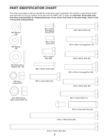
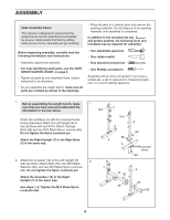
ASSEMBLY Make Assembly Easier This manual is designed to ensure that the weight bench can be assembled successfully by anyone. Most people find that by setting aside plenty of time, assembly will go smoothly. Before beginning assembly, carefully read the following information and instructions: • Assembly requires two persons. • For help identifying small parts, see the PART IDENTIFICATION CHART on page 5. • Tighten all parts as you assemble them, unless instructed to do otherwise. • As you assemble the weight bench, make sure all parts are oriented as shown in the drawings. • Place all parts in a cleared area and remove the packing materials. Do not dispose of the packing materials until assembly is completed. In addition to the included hex key and grease packets, the following tools (not included) may be required for assembly: • Two adjustable spanners • One rubber mallet • One standard screwdriver • One Phillips screwdriver Assembly will be more convenient if you have a socket set, a set of open-end or closed-end spanners, or a set of ratchet spanners. 1. Before assembling the weight bench, make 1 sure that you have read and understand the information in the box above. 7 Nut Orient the Left Base (4) with the recessed holes facing downward. Attach the Left Upright (6) to the Left Base with two M10 x 63mm Carriage Bolts (68) and two M10 Black Nylon Locknuts (66). Do not tighten the Nylon Locknuts yet. Attach the Right Upright (7) to the Right Base (5) in the same way. 2. Attach the Crossbar (12) to the Left Upright (6) 2 with two M10 x 65mm Bolts (55), two M10 Black Washers (64), and two M10 Black Nylon Locknuts (66). Do not tighten the Nylon Locknuts yet. Attach the Crossbar (12) to the Right Upright (7) in the same way. See steps 1-2. Tighten the M10 Black Nylon Locknuts (66). Nut 6 66 66 5 4 Recessed Holes 68 7 6 12 66 64 66 55 6
-
 1
1 -
 2
2 -
 3
3 -
 4
4 -
 5
5 -
 6
6 -
 7
7 -
 8
8 -
 9
9 -
 10
10 -
 11
11 -
 12
12 -
13
-
14
-
15
-
16
-
17
-
18
-
19
-
20
 |
 |
