Weider 245 Bench Uk Manual - Page 7
six M10 Black Washers 64, and four M10
 |
View all Weider 245 Bench manuals
Add to My Manuals
Save this manual to your list of manuals |
Page 7 highlights
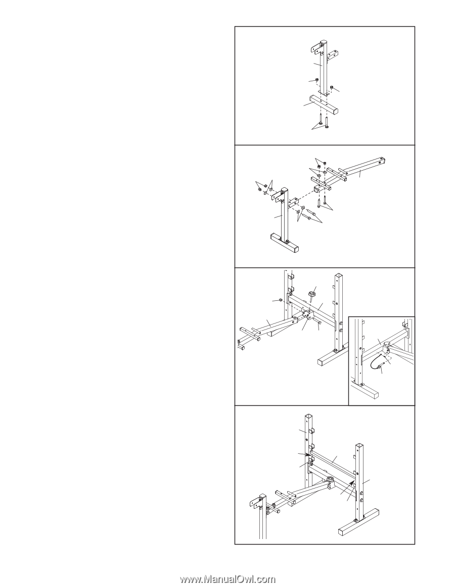
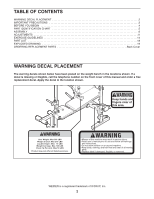
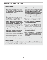
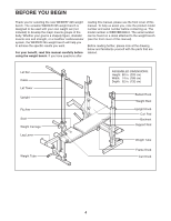
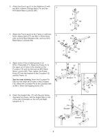
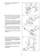
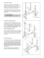
3. Attach the Front Leg (2) to the Stabilizer (3) with two M10 x 58mm Carriage Bolts (74) and two 3 M10 Black Nylon Locknuts (66). 4. Attach the Front Leg (2) to the Frame (1) with two M10 x 60mm Bolts (57), two M10 x 55mm Bolts (59), six M10 Black Washers (64), and four M10 Black Nylon Locknuts (66). 4 66 64 2 66 3 74 66 64 66 1 2 64 59 57 5. Apply some of the included grease to an 5 M10 x 70mm Bolt (71). Attach the Frame (1) to 37 the upper set of holes in the bracket on the Crossbar (12) with the Bolt and an M10 Black Nylon Locknut (66). Then, tighten the Frame 66 12 Knob (37) into the bracket on the Crossbar (12) 1 and the Frame (1). See the inset drawing. Insert the Crossbar Pin Bracket 71 (29) into the lower set of holes in the Crossbar (12). Attach the Crossbar Pin to the Crossbar with an M4 x 16mm Self-tapping Screw (75). 12 75 29 6. Orient the Support Bar (17) with the pins facing 6 downward as shown. Set the Support Bar in one of the sets of brackets on the Left and Right Uprights (6, 7). 7 Pin Bracket 17 6 Pin Bracket 7
-
 1
1 -
 2
2 -
 3
3 -
 4
4 -
 5
5 -
 6
6 -
 7
7 -
 8
8 -
 9
9 -
 10
10 -
 11
11 -
 12
12 -
13
-
14
-
15
-
16
-
17
-
18
-
19
-
20
 |
 |