Weider 3000 Instruction Manual - Page 10
Seat Assembly, Cable Assembly
 |
View all Weider 3000 manuals
Add to My Manuals
Save this manual to your list of manuals |
Page 10 highlights
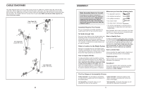
11. Grease an M10 x 51mm Bolt (66). Attach a Cable Pivot (39) to the Right Arm (9) with the Bolt and an M10 Nylon Locknut (56). Do not overtighten the Locknut; the Cable Pivot must be able to pivot easily. Wet the inside of a Large Foam Pad (42) with soapy water. Slide the Large Foam Pad onto the Right Arm (9). Attach the lower end of a Handle (11) to the Right Arm (9) with an M10 x 45mm Button Bolt (77) and an M10 Large Washers (80). Press a 50mm Round Handle Cap (31) into the Right Arm. Do not tighten the Bolt yet. Attach the upper end of the Handle (11) to the Right Arm (9) with an M10 x 67mm Button Bolt (71), two M10 Washers (57), two 12mm Spacers (52), and an M10 Nylon Locknut (56). Tighten the M10 x 45mm Button Bolt (77). Assemble the Left Arm (10) in the same manner. 12. Grease an M10 x 85mm Bolt (67) and two Arm Bushings (44). Attach the Right Arm (9) to the Pivot Frame (5) with the Bolt, two M10 Washers (57), the two Arm Bushings, and an M10 Nylon Locknut (56). Do not overtighten the Locknut; the Arm must be able to pivot easily. Attach the Left Arm (10) to the Pivot Frame (5) in the same manner. 11 52 57 57 56 52 9 66 Grease 39 71 56 10 11 42 31 80 77 12 67 Grease 57 5 9 44 44 57 56 Grease 10 Cable Assembly 13 13. Refer to the CABLE DIAGRAMS on page 20 as you assemble the cables and to identify the cables. Locate the Arm Cable (54). Grease an M8 x 22mm Shoulder Bolt (65). Attach the Cable to the indicated Cable Pivot (39) with the Bolt and an M8 Nylon Locknut (58). Make sure that the Cable can pivot easily around the Bolt. 10 58 39 54 Grease 65 Seat Assembly 30 30. Attach the Backrest (16) to the Upright (3) with two M6 x 63mm Screws (70) and two M6 Washers (82). 16 3 70 82 82 70 31. Attach the Seat (15) to the Seat Frame (6) with 31 two M6 x 63mm Screws (70) and two M6 Washers (82). 15 6 82 82 70 70 32. Attach the Lock Plate (73) to the Front Leg (7) with an M10 x 70mm Bolt (86), an M10 Washer (57), and an M10 Nylon Locknut (56). Do not overtighten the Locknut; the Lock Plate must be able to pivot easily. 32 56 57 69 Attach the Leg Lever Pin (38) to the Front Leg (7) with an M4 x 20mm Self-tapping Screw (69). Insert the Leg Lever Pin through the Leg Lever (8) and the Lock Plate (73). 38 8 73 86 7 33. Insert the Pad Tube (29) through the Front Leg (7). Slide two Small Foam Pads (28) onto the ends of the Pad Tube. Press two Foam Caps (34) onto the Pad Tube. Slide two Small Foam Pads (28) onto the Leg Lever (8). Press two Foam Caps (34) onto the Leg Lever. 33 34 28 15 29 34 28 8 28 34
-
 1
1 -
2
-
3
-
4
-
 5
5 -
 6
6 -
 7
7 -
 8
8 -
 9
9 -
 10
10 -
 11
11 -
 12
12 -
 13
13 -
 14
14
 |
 |
