Weider 3000 Instruction Manual - Page 6
Frame Assembly, WEIGHT RESISTANCE CHART
 |
View all Weider 3000 manuals
Add to My Manuals
Save this manual to your list of manuals |
Page 6 highlights
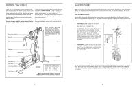
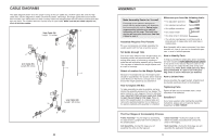
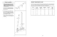
Frame Assembly 1 1. Before beginning assembly, make sure you understand the information in the box on page 5. Refer to the PART IDENTIFICATION CHART in the centre of this manual for help identifying small parts. Insert four M8 x 63mm Carriage Bolts (78) up through the Base (1). Note: It may be helpful to place a piece of tape over the bolt heads to hold them in place. 2. Attach the Base (1) and the two Weight Guides 2 (21) to the Stabiliser (2) with two M10 x 67mm Bolts (71), two M10 Washers (57), and two M10 Nylon Locknuts (56). Make sure the indicated holes in the Weight Guides are nearer the bot- tom. Fully tighten the Locknuts. Attach the Upright (3) to the Base (1) with the indicated two M8 x 63mm Carriage Bolts (78) and two M8 Nylon Locknuts (58). Do not tighten the Locknuts yet. 1 78 78 WEIGHT RESISTANCE CHART The chart below shows the approximate weight resistance at each exercise station. "Top" refers to the 6 lb. top weight. The other numbers refer to the 12.5 lb. weight plates. Weight resistance shown for the butterfly arm station is for each arm. Note: The actual resistance at each station may vary due to differences in individual weight plates as well as friction between the cables, pulleys, and weight guides. WEIGHT Top 1 2 3 4 5 6 HIGH PULLEY (lbs.) 11 26 42 61 70 86 101 BUTTERFLY ARM (lbs.) 16 22 30 41 51 63 82 PRESS ARM (lbs.) 27 44 62 97 127 144 173 LEG LEVER (lbs.) 27 57 85 111 159 182 214 LOW PULLEY (lbs.) 26 55 86 119 148 163 187 21 3 58 71 58 71 1 78 Holes 21 57 56 57 2 6 19
-
 1
1 -
 2
2 -
 3
3 -
 4
4 -
 5
5 -
 6
6 -
 7
7 -
 8
8 -
 9
9 -
 10
10 -
 11
11 -
 12
12 -
13
-
14
 |
 |
