Weider 3000 Instruction Manual - Page 9
Arm Assembly
 |
View all Weider 3000 manuals
Add to My Manuals
Save this manual to your list of manuals |
Page 9 highlights
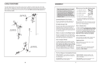
34. Orient the Curl Pad (14) so that the holes on the 34 back are closer to the lower edge. Attach the Curl Pad to the Curl Post (13) with two M6 x 16mm Screws (62). 14 13 62 35. Make sure that all parts have been properly tightened. The use of the remaining parts will be explained in ADJUSTMENTS, beginning on the following page. Before using the weight system, pull each cable a few times to make sure that the cables move smoothly around the pulleys. If one of the cables does not move smoothly, find and correct the problem. IMPORTANT: If the cables are not properly installed, they may be damaged when heavy weight is used. See the CABLE DIAGRAMS on page 20 of this manual for proper cable routing. If there is any slack in the cables, you will need to remove the slack by tightening the cables. See MAINTENANCE on page 21. 16 8. Attach the Shroud (17) to the Top Frame (4) with 8 two M6 x 16mm Screws (62) and two M6 4 Washers (82). 82 Attach the Shroud (17) to the brackets on the 62 Stabiliser (2) with two M6 x 16mm Screws (62) and two M6 Washers (82). Make sure the brack- ets are inside the Shroud. 62 82 Tighten the Nylon Locknuts (56, 58) used in steps 2-7. 62 82 17 Bracket Arm Assembly 9. Grease the M10 x 77mm Bolt (79). Orient the Leg Lever (8) with the welded support as shown. Attach the Leg Lever to the Front Leg (7) with the Bolt and an M10 Nylon Locknut (56). Do not overtighten the Locknut; the Leg Lever must be able to pivot easily. 9 56 8 Welded Support 2 82 62 7 Grease 79 10. Grease the M10 x 77mm Bolt (79). Attach the Pivot Frame (5) to the Top Frame (4) with the Bolt and an M10 Nylon Locknut (56). Do not overtighten the Locknut; the Pivot Frame must be able to pivot easily. Attach the two Arm Pins (40) to the Pivot Frame (5) with two M4 x 20mm Self-tapping Screws (69). Insert the Arm Pins into the two holes in the Upright (3). 10 56 69 5 40 4 79 Holes Grease 3 69 40 9
-
 1
1 -
2
-
3
-
 4
4 -
 5
5 -
 6
6 -
 7
7 -
 8
8 -
 9
9 -
 10
10 -
 11
11 -
 12
12 -
 13
13 -
 14
14
 |
 |
