Weider 3000 Instruction Manual - Page 4
Maintenance, Before You Begin - pro review
 |
View all Weider 3000 manuals
Add to My Manuals
Save this manual to your list of manuals |
Page 4 highlights
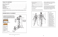
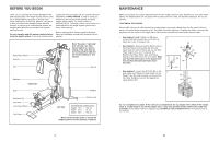
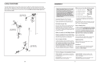
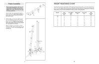
BEFORE YOU BEGIN Thank you for selecting the versatile WEIDER® PRO 3000 weight system. The weight system offers a selection of weight stations designed to develop every major muscle group of the body. Whether your goal is to tone your body, build dramatic muscle size and strength, or improve your cardiovascular system, the weight system will help you to achieve the specific results you want. For your benefit, read this manual carefully before using the weight system. If you have questions after reading this manual, please call our Customer Service Department at 08457 089 009. To help us assist you, please note the product model number and serial number before calling. The model number is WEEVSY1975.0. The serial number can be found on a decal attached to the weight system (see the front cover of this manual). Before reading further, please review the drawing below and familiarise yourself with the parts that are labelled. High Pulley Station Arm Pin Note: The terms "right side" and "left side" are determined relative to a person sitting on the seat; they do not correspond to right and left on the drawings in this manual. Arm Shroud Backrest Seat Right Side Leg Lever Pin Leg Lever Low Pulley Station Foot Plate Weights *Anchor Hole Left Side ASSEMBLED DIMENSIONS: Height: 76 in. / 193 cm Width: 37 in. / 94 cm Depth: 48 in. / 122 cm *Note: Use the anchor holes to secure the weight system to a fixed position, if desired. 4 MAINTENANCE Make sure all parts are properly tightened each time the weight system is used. Replace any worn parts immediately. The weight system can be cleaned with a damp cloth and a mild, non-abrasive detergent. Do not use solvents. TIGHTENING THE CABLES Woven cable, the type of cable used on the weight system, can stretch slightly when it is first used. If there is slack in the cables before resistance is felt, the cables should be tightened. To tighten the cables, first insert the weight pin into the middle of the weight stack. Slack can be removed from these cables several ways: • See drawing 1 inset. Tighten the M8 Nylon 1 Locknut (58) that connects the end of the Low Cable (53) to the "U"-bracket (45). • See drawing 1. Remove the M10 Nylon Locknut (56) and the M10 x 51mm Bolt (66) from the Cable Trap (51), 90mm Pulley (48), the two Half Finger Guards (43), and "U"-bracket (45). Reattach the Pulley, Cable Trap, and Finger Guards to the other hole in the "U"-bracket. Make sure that the Cable Trap is in the proper position and that the Cable and Pulley move smoothly. 45 • See drawing 2. Loosen the M12 Nut (84) on the 2 High Cable (55). Tighten the High Cable into the Weight Tube (24) until the slack is removed from the Cable. Retighten the M12 Nut against the Large Washer (85). 56 43 48 51 43 66 58 45 53 53 55 84 85 24 Do not overtighten the cables. If the cables are overtightened, the top weight will be lifted off the weight stack. If a cable tends to slip off the pulleys often, it may have become twisted. Remove the cable and re-install it. If the cables need to be replaced, see ORDERING REPLACEMENT PARTS on the back cover of this manual. 21
-
 1
1 -
 2
2 -
 3
3 -
 4
4 -
 5
5 -
 6
6 -
 7
7 -
 8
8 -
 9
9 -
 10
10 -
11
-
12
-
13
-
14
 |
 |
