Weider 3000 Instruction Manual - Page 8
Adjustments
 |
View all Weider 3000 manuals
Add to My Manuals
Save this manual to your list of manuals |
Page 8 highlights
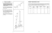
6. Attach the Top Frame (4) to the Upright (3) with 6 two M8 x 65mm Bolts (68), two M8 Washers (59), and two M8 Nylon Locknuts (58). Do not tighten the Locknuts yet. Attach the Top Frame (4) between the Weight Guides (21) with an M10 x 155mm Bolt (74), two M10 Washers (57), two 19mm Spacers (76), and an M10 Nylon Locknut (56). Do not tighten the Locknuts yet. 7. Attach the Left Cap (19) and the Right Cap (20) 7 to the bottom of the Shroud (17) with two M5 x 20mm Self-tapping Screws (64) and two M5 Washers (72). Attach the Top Cap (18) to the top of the Shroud (17) with two M6 x 16mm Screws (62), four M6 Washers (82), and two M6 Locknuts (87). 68 56 57 76 59 4 57 74 58 58 3 21 21 62 82 87 18 82 62 17 20 72 64 72 19 8 ADJUSTMENTS This section explains how to adjust the weight system. See the EXERCISE GUIDELINES on page 22 for important information about how to get the most benefit from your exercise program. Also, refer to the accompanying exercise guide to see the correct form for each exercise. Make sure all parts are properly tightened each time the weight system is used. Replace any worn parts immediately. The weight system can be cleaned with a damp cloth and a mild, non-abrasive detergent. Do not use solvents. CHANGING THE WEIGHT SETTING To change the setting of a weight stack, insert a Weight Pin (26) under the desired Weight (22). Insert the Weight Pin so that the bent end touches the Weight. Turn the bent end down. Note: Do not use the Top Weight (25) by itself. Note: Due to the cables and pulleys, the amount of resistance at each exercise station may vary from the weight setting. Use the WEIGHT RESISTANCE CHART on page 19 to find the approximate amount of resistance at each weight station. 25 22 26 ATTACHING THE ACCESSORIES TO A PULLEY STATION Attach the Handle Strap (91) to the Low Cable (53) at the low pulley station with a Cable Clip (37). For some exercises, the Chain (90) should be attached between the Handle Strap and the Cable with two Cable Clips. Adjust the length of the Chain between the Handle Strap and the Cable so that the Handle Strap is in the correct starting position for the exercise to be performed. The Lat Bar (not shown) or the Handle Strap (91) can be attached at either pulley station in the same manner. Always engage the Lock Plate (73) when using the high pulley station (see USING THE LOCK LEVER below). 73 37 90 53 37 91 USING THE LOCK LEVER When using the low pulley station, engage the Leg Lever Pin (38) into the Leg Lever (8) and the Lock Plate (73). To use the Leg Lever (8), engage the Leg Lever Pin (38) into the Front Leg (7) and the Lock Plate (73). 38 8 73 7 17
-
 1
1 -
2
-
 3
3 -
 4
4 -
 5
5 -
 6
6 -
 7
7 -
 8
8 -
 9
9 -
 10
10 -
 11
11 -
 12
12 -
 13
13 -
14
 |
 |
