Weider Pro 435 Bench Uk Manual - Page 7
en the Nylon Locknuts yet. Note: If the Upright
 |
View all Weider Pro 435 Bench manuals
Add to My Manuals
Save this manual to your list of manuals |
Page 7 highlights
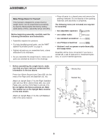
2. Orient the Crossbar (3) as shown. Attach the Crossbar to the left Upright Base (7) with four M10 x 80mm Bolts (35), two Joint Plates (20), and four M10 Nylon Locknuts (19). Do not tighten the Nylon Locknuts yet. Note: If the Upright (not shown) has been preassembled, lift it out of the way of the bolts going through the Upright Base. Attach the Crossbar (3) to the right Upright Base (not shown) in the same manner. 2 3 35 20 19 7 20 19 3. Press a 50mm Square Inner Cap (54) halfway into the top of the Front Leg. Press two 40mm x 50mm Inner Caps (68) into the Stabiliser (66). 3 Orient the Stabiliser (66) with the indents around the holes on the bottom. Attach the Stabiliser to the Front Leg (8) with two M10 x 52mm Carriage Bolts (64) and two M10 Nylon Locknuts (19). Do not tighten the Nylon Locknuts yet. Attach the Front Leg (8) to the Bench Frame (2) with two M10 x 70mm Bolts (18), the Support Plate (14), and two M10 Nylon Locknuts (19). Do not tighten the Nylon Locknuts yet. 4. Lubricate an M10 x 75mm Bolt (51). Attach the 4 Bench Frame (2) to the upper set of holes in the bracket on the Crossbar (3) with the Bolt, two M10 Washers (24), and an M10 Nylon Locknut (19). Do not overtighten the Nylon Locknut; the Bench Frame must be able to pivot easily. Insert the Ring Pin (43) into the lower set of holes in the bracket on the Crossbar (3). Tighten the M10 x 57mm Adjustment Knob (33) into the Crossbar and Bench Frame (2). Tighten all of the M10 Nylon Locknuts (19) used in steps 1-3. 54 14 19 19 68 Indents 64 18 2 18 8 19 66 68 Lubricate 51 33 Bracket 19 3 24 2 43 5. Press three 45mm Square Inner Caps (21) into the Leg Lever (4). Slide the Weight Tube (41) through the Leg Lever (4) and secure it with an M8 x 57mm Bolt (39), two M8 Washers (38), a Small Spacer (37), and an M8 Nylon Locknut (13). Press a 25.4mm Round Inner Cap (23) into the indicated end of the Weight Tube (41). Press the 25.4mm Angled Cap (29) onto the other end of the Weight Tube. 5 21 4 37 39 38 21 23 41 21 29 13 38 7
-
 1
1 -
 2
2 -
 3
3 -
 4
4 -
 5
5 -
 6
6 -
 7
7 -
 8
8 -
 9
9 -
 10
10 -
 11
11 -
 12
12 -
13
-
14
-
15
-
16
-
17
-
18
-
19
-
20
 |
 |
