Weider Pro 435 Bench Uk Manual - Page 8
tighten the Nylon Locknut; the Leg Lever
 |
View all Weider Pro 435 Bench manuals
Add to My Manuals
Save this manual to your list of manuals |
Page 8 highlights
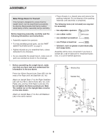
6. Lubricate an M10 x 70mm Bolt (18). Attach the 6 Leg Lever (4) to the Front Leg (8) with the Bolt and an M10 Nylon Locknut (19). Do not over- tighten the Nylon Locknut; the Leg Lever must be able to pivot easily. 19 4 18 Lubricate 8 7. Identify the Right and Left Backrest Frames (5, 42) by the position of the adjustment tubes, and orient them as shown. Tap two 25.4mm Square Inner Caps (12) into the ends of each Backrest Frame. Tap a 25mm x 50mm Inner Cap (36) into the bottom of each adjustment tube. Orient the Backrest (6) with the wide end on the side shown. Attach the Backrest to the Right and Left Backrest Frames (5, 42) with four M6 x 38mm Bolts (16) and four M6 Washers (25). Do not tighten the Bolts yet. 8. Lubricate the M10 x 175mm Bolt (17). Attach the Backrest Frames (5, 42) to the Bench Frame (2) with the Bolt, two M10 Washers (24), and an M10 Nylon Locknut (19). Do not overtighten the Nylon Locknut; the Backrest (6) must be able to pivot easily. Secure the Backrest (6) to the Bench Frame (2) by inserting the Adjustment Pin (32) through the tube in the Bench Frame and a set of holes in the adjustment tubes. Make sure that the Adjustment Pin is completely inserted through both adjustment tubes. Tighten the four M6 x 38mm Bolts (16) used in step 7. 7 6 Wide End 12 5 12 25 16 36 8 42 25 25 16 Adjustment Tubes 25 16 6 5 32 42 Adjustment Tubes 17 24 Tube 24 2 19 8
-
 1
1 -
2
-
 3
3 -
 4
4 -
 5
5 -
 6
6 -
 7
7 -
 8
8 -
 9
9 -
 10
10 -
 11
11 -
 12
12 -
 13
13 -
14
-
15
-
16
-
17
-
18
-
19
-
20
 |
 |
