Weider Pro 550 Bench Uk Manual - Page 10
Bolt Set 64. Attach the Leg Lever 18 to - press
 |
View all Weider Pro 550 Bench manuals
Add to My Manuals
Save this manual to your list of manuals |
Page 10 highlights
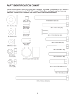
11. Attach the Weight Tube (19) to the Leg Lever 11 (18) with an M8 x 58mm Bolt (46), two M8 Washers (50), a 12mm x 10mm Spacer (61), and an M8 Nylon Locknut (49). Press the 25mm Round Outer Cap (62) onto the end of the Weight Tube (19). 12. Apply grease to the barrel of an M10 x 57mm 12 Bolt Set (64). Attach the Leg Lever (18) to the Front Leg (12) with the Bolt Set. Make sure the barrel of the Bolt Set passes completely through the bracket. Do not overtighten the Bolt Set; the Leg Lever must pivot easily. 61 49 50 19 18 62 50 46 Grease 64 18 64 Bracket 12 13. Locate the Pad Tube (24) that has a 19mm Round Inner Cap (71) in each end. Insert the Pad Tube into either hole in the Front Leg (12). Slide two Foam Pads (23) onto the Pad Tube. Insert a Pad Tube (24) into one of the holes in the Leg Lever (18). Slide two Foam Pads (23) onto the Pad Tube, and press a Pad Cap (25) into the end of each Foam Pad. Repeat with the other Pad Tube (24). 14. Route the Cable (73) under the indicated welded rod, through the Lat Tower (14), and over the the Pulley (69). Attach the Pulley to the Lat Tower with an M10 x 60mm Bolt (68), two M10 Washers (43), two 15mm x 10mm Spacers (70), and an M10 Nylon Locknut (58). Do not overtighten the Nylon Locknut; the Pulley must turn easily. 13 23 18 71 24 25 23 14 43 58 70 71 12 24 23 24 23 25 Welded Rod 70 69 73 43 68 14 10
-
 1
1 -
2
-
3
-
4
-
 5
5 -
 6
6 -
 7
7 -
 8
8 -
 9
9 -
 10
10 -
 11
11 -
 12
12 -
 13
13 -
 14
14 -
 15
15 -
16
-
17
-
18
-
19
-
20
 |
 |
