Weider Pro 9725 English Manual
Weider Pro 9725 Manual
 |
View all Weider Pro 9725 manuals
Add to My Manuals
Save this manual to your list of manuals |
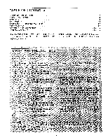
Weider Pro 9725 manual content summary:
- Weider Pro 9725 | English Manual - Page 1
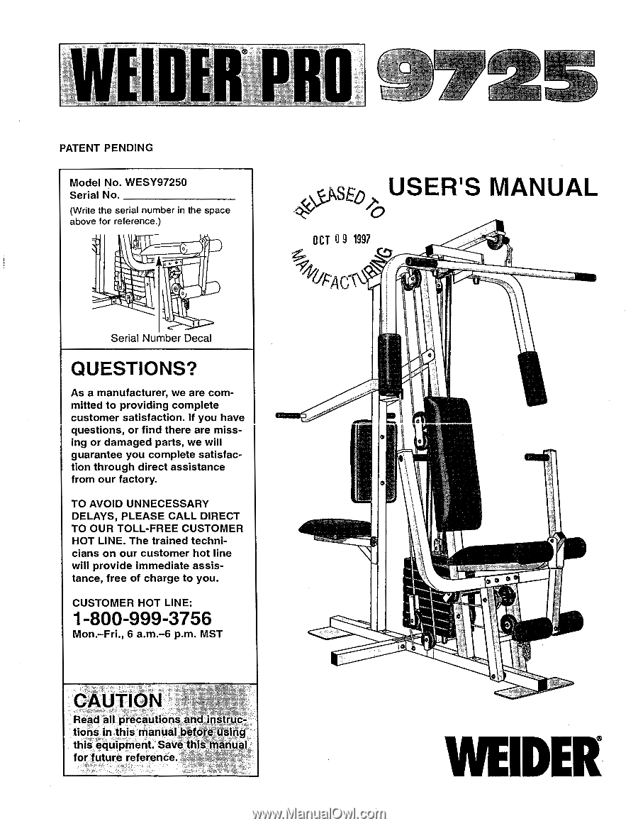
. If you have questions, or find there are missing or damaged parts, we will guarantee you complete satisfaction through direct assistance from our factory HOT LINE: 1-800-999-3756 Mon.-Fri., 6 a.m.-6 p.m. MST 40E0 USER'S MANUAL )6 OCT a 9 1997 •N"" r +r4AC\ li Ii I 0 jl 4., OE CAUTION Read - Weider Pro 9725 | English Manual - Page 2
are attached to the center of this manual. Remove the EXPLODED DRAWING/PART LIST and the PART IDENTIFICATION CHART before beginning assembly. IMPORTANT> PRECAUTIONS WARNING: To reduce the risk of serious injury, read the following important precautions before using the,home gym system. "It is the - Weider Pro 9725 | English Manual - Page 3
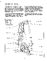
, read this manual carefully before using the WEIDER® PRO 9725 Home Gym System. If you have additional questions, please call our Customer Service Department toll-free at 1-800-999- Before reading further, please review the drawing below and familiarize yourself with the parts that are labeled - Weider Pro 9725 | English Manual - Page 4
assembly, use the PART IDENTIFICATION CHART located in the center of this manual. Note: Some small parts may have been preattached for shipping. If a part is not in the parts bag, check to see if it has been pre-attached. • As you assemble the home gym system, be sure that all parts are oriented as - Weider Pro 9725 | English Manual - Page 5
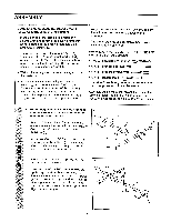
3. Press a 2" Square Inner Cap (27) into the 3 Rear Upright (56). Attach a Rubber Bumper (90) to the Rear Upright (56) with a #8 x 1/2" Tap Screw (89). Slide the Rear Upright (56) onto the 5/16" x 2 1/2" Carriage Bolts (1) in the Rear Base (51). Hand tighten a 5/16" Nylon Locknut (3) onto each - Weider Pro 9725 | English Manual - Page 6
at the top, as shown. Press a 1" Round Cover Cap (70) onto the bottom of each Weight Guide (62). Slide eight Weights (25) on the Weight Guides (62). Be sure that all of the Weights are turned so the pin grooves are on the same side. Drilled holes must be at the top 62 Pin Grooves must - Weider Pro 9725 | English Manual - Page 7
RAME ASSEMBLY 8. Attach the upper ends of the Weight Guides 8 (62) to the Top Frame (55) with the 5/16" x 6" Bolt (60), two 1/2" x 3/4" Spacers (61), and a 5/16" Nylon Locknut (3). Tighten all Nylon Locknuts used in steps 2 - Weider Pro 9725 | English Manual - Page 8
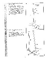
12. Lubricate both axles on the Top Frame (55). Slide the Right Arm (48) onto the right axle. Note: Be careful not to confuse the Right Arm with the Left Arm (47); refer to step 11 to identify the Right Arm. Be sure that the upper end of the Right Arm is behind the indicated bracket on the Top Frame - Weider Pro 9725 | English Manual - Page 9
14. During steps 15 through 36, refer to the CABLE DIAGRAM on page 23 of this manual to verify proper cable routing. Before beginning this section, identify the Long Cable (86), the Medium Cable (23), and the Short Cable (58) by comparing - Weider Pro 9725 | English Manual - Page 10
18. Route the Medium Cable (23) around the "V"Pulley (6) on the Right Arm (48). Be sure 18 that the Cable is in the groove of the "V"- Pulley and that the Long Cable Trap (50) is turned to hold the Cable in place. Tighten the 3/8" x 2 1/2" Bolt (7) and the 3/8" Nylon Locknut (not shown). 7 O - Weider Pro 9725 | English Manual - Page 11
21. Wrap the Medium Cable (23) around a 3 1/2" 21 Pulley (15). Attach the Pulley to the Top Frame (55) with a 3/8" x 1 3/4" Bolt (87) and a 3/8" Nylon Locknut (21). 55; 21 15 23 0 22. Wrap the Medium Cable (23) around a 3 1/2" Pulley (15). Attach the Pulley to the Top 22 Frame (55) with a - Weider Pro 9725 | English Manual - Page 12
25. Attach the end of the Short Cable (58) to the Long "U"-Bracket (57) with a 1/4" Nylon Lock- 25 nut (2) and a 1/4" Flat Washer (10). Do not completely tighten the Nylon Locknut. It should be threaded onto the end of the Cable so only a couple of threads are showing above the nut, as shown - Weider Pro 9725 | English Manual - Page 13
27. Locate the Long Cable (86). Route the Long Cable under the 3 1/2" Low Pulley (88). Be sure that the end of the Cable with the ball is on the indicated side of the Press Frame (17) and that the Cable is between the Pulley and the crossbar on the Press Frame. Tighten the 3/8" Nylon Locknut (21) - Weider Pro 9725 | English Manual - Page 14
31. Wrap the Long Cable (86) around a 3 1/2" Pulley (15). Attach the Pulley and a Cable Trap (66) to the Press Frame (17) with a 3/8" x 3 1/2" Bolt (16), a 3/8" Flat Washer (9), and a 3/8" Nylon Locknut (21). Be sure that the Cable Trap is turned to hold the Cable in place and that the Cable is - Weider Pro 9725 | English Manual - Page 15
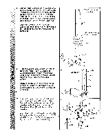
with a 5/16" x 2 3/4" Bolt (11), a 5/16" Flat Washer (8), and a 5/16" Nylon Locknut (3). 86 4 11 8 3 36. Attach the Small "U"-Bracket (67) to the 36 Weight Tube (63) with the 5/16" x 1 3/4" Bolt (72) and a 5/16" Nylon Locknut (3). 3 67 72 63 37. Attach the Small Backrest (80) to the Rear - Weider Pro 9725 | English Manual - Page 16
38. Press a 1 3/4" Square Inner Cap (44) into the Rear Seat Frame (77). Insert the 1/4" x 2 1/2" Carriage Bolt (91) into the center hole in a Seat Plate (37). Attach the Seat Plate to a Seat (13) with two 1/4" x 1/2" Screws (18). Insert the 1/4" x 2 1/2" Carriage Bolt (91) into the indicated hole in - Weider Pro 9725 | English Manual - Page 17
41. Press a 1 1/2" Square Inner Cap (32) into the Front Seat Frame (36). Insert the 1/4" x 2 1/4" Carriage Bolt (38) into the center hole in a Seat Plate (37). Attach the Seat Plate to the Seat (13) with two 1/4" x 1/2" Screws (18). Insert the 1/4" x 2 1/4" Carriage Bolt (38) into the indicated - Weider Pro 9725 | English Manual - Page 18
manual.' Before using the home gym system, pull each cable a few times to be sure that the cables move smoothly over the pulleys. If one of the cables does not move smoothly, find and correct the problem. IMPORTANT: If the cables are not properly installed, they may be damaged when heavy weight - Weider Pro 9725 | English Manual - Page 19
ADJUSTMENT The instructions below describe how each part of the home gym system can be adjusted. Refer to the exercise poster accompanying this manual to see how the home gym system should be set up for each exercise. IMPORTANT: When attaching the lat bar or nylon strap, make sure that the - Weider Pro 9725 | English Manual - Page 20
Carriage Bolt (14) and the Seat Knob (40). 42 40 36 For some exercises, the Front Seat Frame (36) must be removed. First, be sure that the 5/16" x 2 3/4" Carriage Bolt (14) and the Seat Knob (40). For some exercises, the Rear Seat Frame (77) must B be removed. Remove the Seat Knob (40) and - Weider Pro 9725 | English Manual - Page 21
WEIGHT RESISTANCE CHART This chart shows the approximate weight resistance at each station. "Top" refers to the 6.5 lb. top weight. The other numbers refer to the 12.5 lb. weight plates. Weight resistance shown for the butterfly arm station is for each butterfly arm. WEIGHT PLATES PRESS ARM (lbs.) - Weider Pro 9725 | English Manual - Page 22
assembled correctly. If the cables have not been correctly routed, the home gym system will not function properly and damage may occur. The numbers show 14) Short Cable (58) Rear Upright-1 6 2 0 5 7 4 O Weight Stack Long "U"-Bracket-3 7to'1; 0 9 Base-10 8 Long Cable (86) 6 4 3 2 5 - - Weider Pro 9725 | English Manual - Page 23
TROUBLE-SHOOTING AND MAINTENANCE Inspect and tighten all parts each time you use the home gym system. Replace any worn parts immediately. The home gym need to remove the Small "U"-Bracket (67) from the Weight Tube (not shown) or remove the 3 1/2" Pulley ( PARTS on the back cover of this manual. 22 - Weider Pro 9725 | English Manual - Page 24
9725 Home Gym System). 3. The SERIAL NUMBER of the product (see the front cover of this manual). 4. The KEY NUMBER and DESCRIPTION of the part(s) (see the PART or abnormal usage or repairs not provided by an ICON authorized service center, products used for commercial or rental purposes, or products - Weider Pro 9725 | English Manual - Page 25
REMOVE THIS PART IDENTIFICATION CHART FROM THE MANUAL This chart is provided to help you identify the small parts used in assembly. Important: Some parts may have been pre-assembled for shipping purposes. If you cannot find a part in the parts bags, check to see if it has been pre-assembled. The - Weider Pro 9725 | English Manual - Page 26
0 El 1/4" Nylon Locknut (2)-4 5/16" Nylon Jam Nut (84)-2 Cod 5/16" Nylon Locknut (3)-22 0 3/8" Nylon Locknut (21)-20 1/4" Flat Washer (10)-10 5/16" Flat Washer (8)-11 3/8" Flat Washer (9)-7 0 1/4" x 2 1/4" Carriage Bolt (38)-1 1/4" x 2 1/2" Screw (43)-5 1/4" x 2 1/2" Carriage Bolt ( - Weider Pro 9725 | English Manual - Page 27
1/2" x 314" Spacer (61)-2 5/16" x 1 3/4" Bolt (72)-1 \\\\\\\\ 3/8" x 1 3/4' Bolt (87)-4 1 1/8" x 2 1/2" Plastic Bushing (74)-2 1/2" x 17/32" Spacer (24)-2 5/8" x 9/16" Spacer (73)-1 3/8" x 2" Bolt (12)-3 3/8" x 2 1/2" Bolt (7)-3 K \ \ \ \ \I \ \\\ 5/16" x 2 1/4" Bolt (33)-1 1" x 7/8" Plastic - Weider Pro 9725 | English Manual - Page 28
3/4" Round Inner Cap (34)-4 1" Round Inner Cap (49)-6 1" Round Cover Cap (70)-4 5/16" x 2" Eyebolt (35)-1 1" Square Inner Cap (65)-1 n-h-h-N1 1 3/4" Square Inner Cap (44)-7 2" Square Inner Cap (27)-6 2 2" Square Cover Cap (78)-2 1 1/2" Square Inner Cap (32)-2 1" x 2" Endcap (83)-2 - Weider Pro 9725 | English Manual - Page 29
- Weider Pro 9725 | English Manual - Page 30
... EXPLODED DRAWING-Model No. WESY97250 11 11 68 27 87 27 55 44151 49 92 31 22 8 92 6-3 49 24-19 9-4 6-3 79 A-21 9 --21 56 31 13 15 66 71 85 P -11 21 87 15 21/ 3 3 -„, 44 61 II (Ck6c612 21 20 15 60 62 K 89 90 37 18 44 10 2 77 t r 14- L10 43 54 31 53 52 80 84 31 - Weider Pro 9725 | English Manual - Page 31
8" Bolt 5/16" x 6" Bolt 1/2" x 3/4" Spacer Weight Guide Weight Tube Weight Tube Bumper 1" Square Inner Cap Cable Trap Small "U"-Bracket Handle 5/16" x 3" Bolt User's Manual Exercise Poster Note: "#" indicates a non-illustrated part. Specifications are subject to change without notice.
-
 1
1 -
 2
2 -
 3
3 -
 4
4 -
 5
5 -
 6
6 -
 7
7 -
8
-
9
-
10
-
11
-
12
-
13
-
14
-
15
-
16
-
17
-
18
-
19
-
20
-
21
-
22
-
23
-
24
-
25
-
26
-
27
-
28
-
29
-
30
-
31
 |
 |
PATENT
PENDING
Model
No.
WESY97250
Serial
No.
(Write
the
serial
number
in
the
space
above
for
reference.)
0
Serial
Number
Decal
QUESTIONS?
As
a
manufacturer,
we
are
com-
mitted
to
providing
complete
customer
satisfaction.
If
you
have
questions,
or
find
there
are
miss-
ing
or
damaged
parts,
we
will
guarantee
you
complete
satisfac-
tion
through
direct
assistance
from
our
factory.
TO
AVOID
UNNECESSARY
DELAYS,
PLEASE
CALL
DIRECT
TO
OUR
TOLL
-FREE
CUSTOMER
HOT
LINE.
The
trained
techni-
cians
on
our
customer
hot
line
will
provide
immediate
assis-
tance,
free
of
charge
to
you.
CUSTOMER
HOT
LINE:
1-800-999-3756
Mon.
—Fri.,
6
a.m.-6
p.m.
MST
CAUTION
Read
all
precautions
and
instruc-
tions
in
this
manual
before
using`
equipment.
Save
t
il
ls
manual
for
future
reference.
•
40E0
USER'S
MANUAL
)
6
OCT
a
9
1997
•N""
+r4
AC\
li
jl
I
r
0
4.,
Ii
OE
WEIDER