Weider Pro 9725 English Manual - Page 13
Weider Pro 9725 Manual
 |
View all Weider Pro 9725 manuals
Add to My Manuals
Save this manual to your list of manuals |
Page 13 highlights
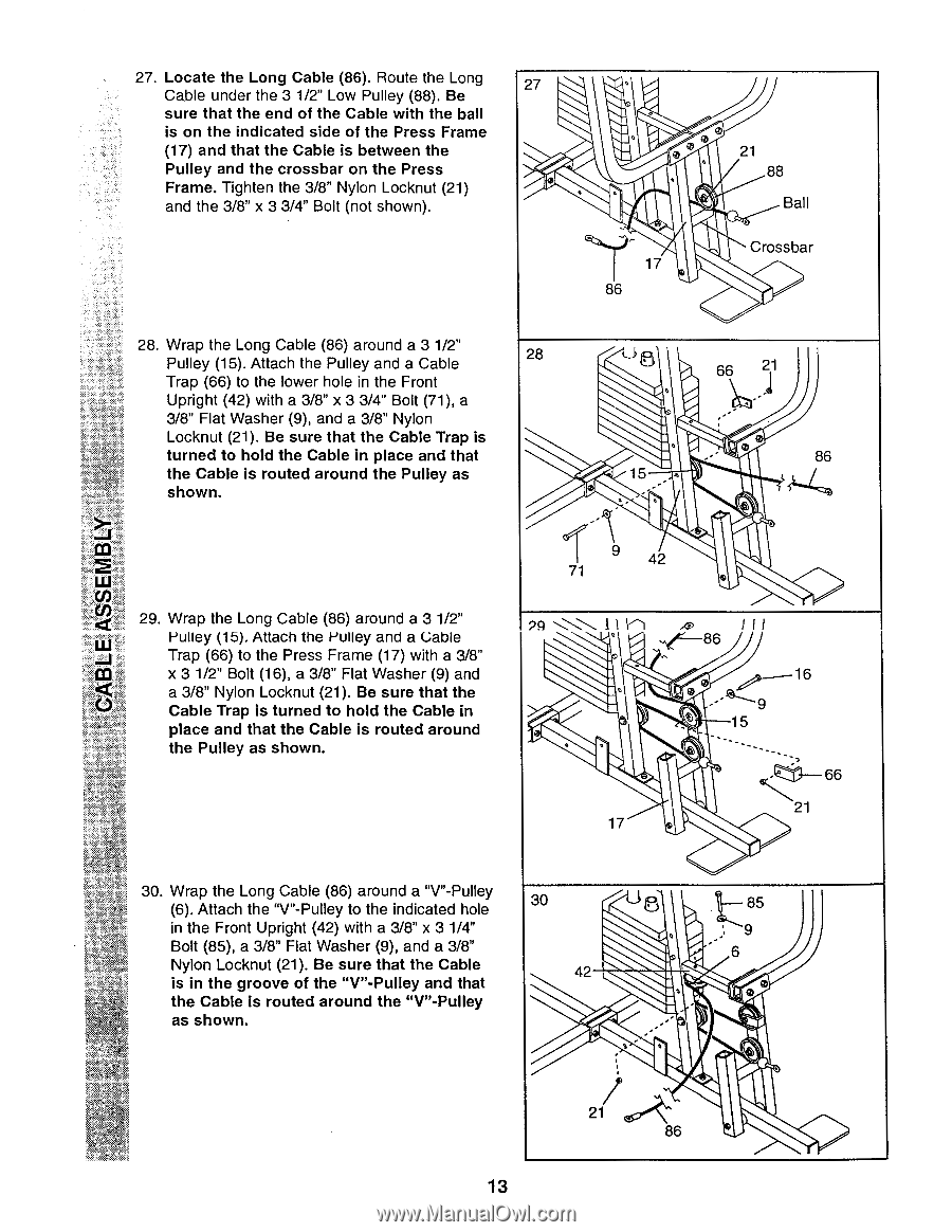
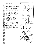
27. Locate the Long Cable (86). Route the Long Cable under the 3 1/2" Low Pulley (88). Be sure that the end of the Cable with the ball is on the indicated side of the Press Frame (17) and that the Cable is between the Pulley and the crossbar on the Press Frame. Tighten the 3/8" Nylon Locknut (21) and the 3/8" x 3 3/4" Bolt (not shown). 27 0 . , e ° cz„..13, 17 86 21 88 Ball Crossbar 28. Wrap the Long Cable (86) around a 3 1/2" Pulley (15). Attach the Pulley and a Cable Trap (66) to the lower hole in the Front Upright (42) with a 3/8" x 3 3/4" Bolt (71), a 3/8" Flat Washer (9), and a 3/8" Nylon Locknut (21). Be sure that the Cable Trap is turned to hold the Cable in place and that the Cable is routed around the Pulley as shown. 29. Wrap the Long Cable (86) around a 3 1/2" Pulley (15). Attach the Pulley and a Gable Trap (66) to the Press Frame (17) with a 3/8" x 3 1/2" Bolt (16), a 3/8" Flat Washer (9) and a 3/8" Nylon Locknut (21). Be sure that the Cable Trap is turned to hold the Cable in place and that the Cable is routed around the Pulley as shown. 28 6 66 21 t, . ,,-- ,-• 86 15 ,. , 9 42 71 ® PA •-...\\ I 1 1 1 ,c, 1 I I ...f 86 . . e A"--- 16 e 1 .._ _11 15 6 e -Zti-- 66 21 17 30. Wrap the Long Cable (86) around a "V"-Pulley (6). Attach the "V"-Pulley to the indicated hole in the Front Upright (42) with a 3/8" x 3 1/4" Bolt (85), a 3/8" Flat Washer (9), and a 3/8" Nylon Locknut (21). Be sure that the Cable is in the groove of the "V"-Pulley and that the Cable is routed around the "V"-Pulley as shown. 30 85 , 6 42 • , ,--' S• 0 21 86 13
-
 1
1 -
2
-
3
-
4
-
5
-
6
-
7
-
 8
8 -
 9
9 -
 10
10 -
 11
11 -
 12
12 -
 13
13 -
 14
14 -
 15
15 -
 16
16 -
 17
17 -
 18
18 -
19
-
20
-
21
-
22
-
23
-
24
-
25
-
26
-
27
-
28
-
29
-
30
-
31
 |
 |