Whirlpool WED6400S Use and Care Manual - Page 14
in Plan Vent System.
 |
UPC - 883049025087
View all Whirlpool WED6400S manuals
Add to My Manuals
Save this manual to your list of manuals |
Page 14 highlights
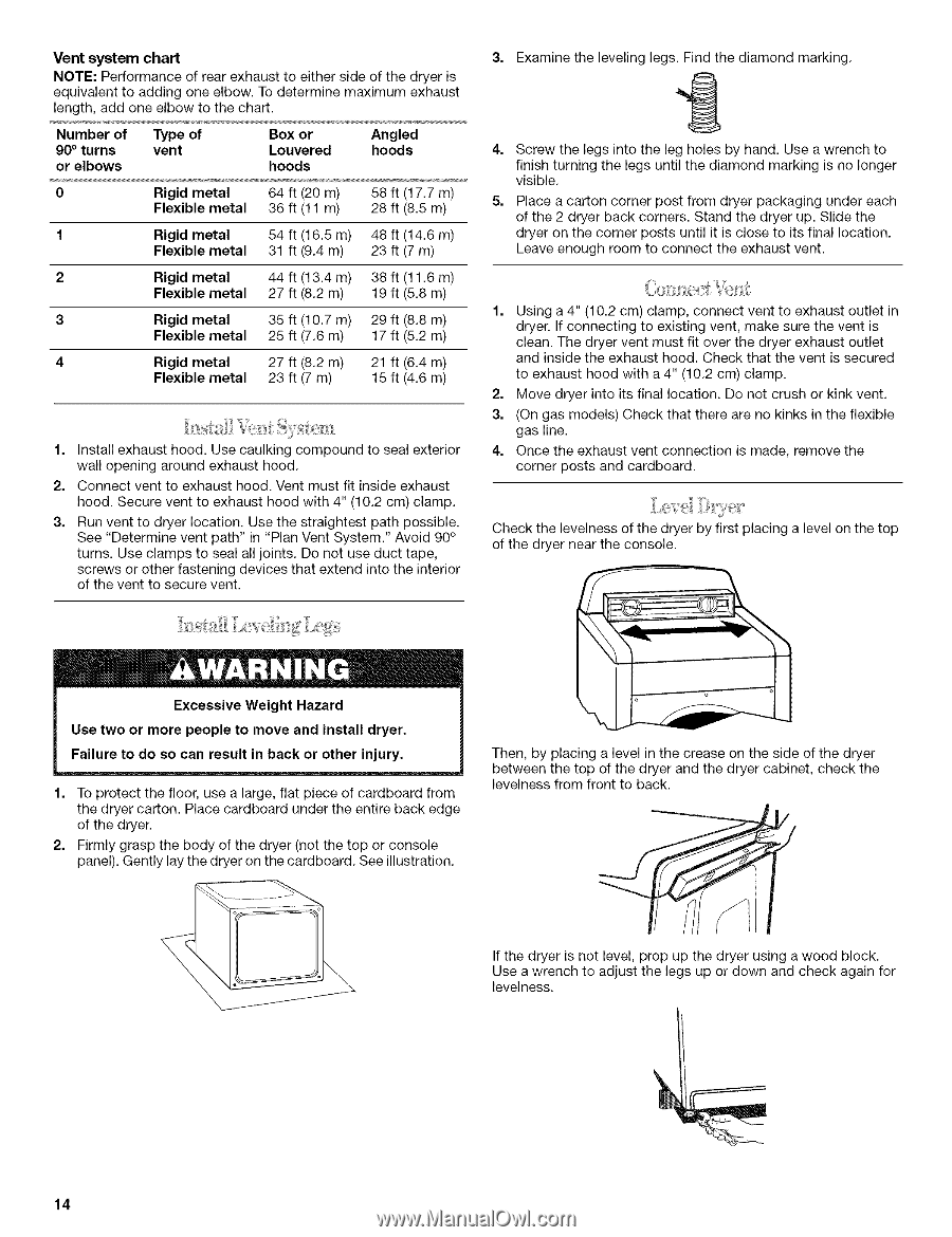
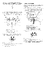
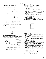
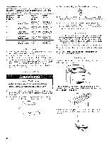
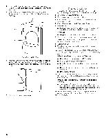
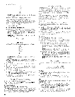
Vent system chart NOTE: Performance of rear exhaust to either side of the dryer is equivalent to adding one elbow. To determine maximum exhaust length, add one elbow to the chart. Number of 90 ° turns or elbows Type of vent Box or Louvered hoods Angled hoods 0 Rigid metal 64 ft (20 m) 58 ft (17,7 m) Flexible metal 36 ft (11 m) 28 ft (8,5 m) 1 Rigid metal 54 ft (16.5 m) 48 ft (14.6 m) Flexible metal 31 ft (9.4 m) 23 ft (7 m) 2 Rigid metal 44 ft (13.4 m) 38 ft (11,6 m) Flexible metal 27 ft (8,2 m) 19 ft (5,8 m) 3 Rigid metal 35 ft (10.7 m) 29 ft (8.8 m) Flexible metal 25 ft (7,6 m) 17 ft (5,2 m) 4 Rigid metal 27 ft (8,2 m) 21 ft (6,4 m) Flexible metal 23 ft (7 m) 15 ft (4,6 m) 1. Install exhaust hood. Use caulking compound to seal exterior wall opening around exhaust hood. 2. Connect vent to exhaust hood. Vent must fit inside exhaust hood. Secure vent to exhaust hood with 4" (10.2 cm) clamp. 3. Run vent to dryer location. Use the straightest path possible. See "Determine vent path" in "Plan Vent System." Avoid 90 ° turns. Use clamps to seal all joints. Do not use duct tape, screws or other fastening devices that extend into the interior of the vent to secure vent. Examine the leveling legs. Find the diamond marking. 4. Screw the legs into the leg holes by hand. Use a wrench to finish turning the legs until the diamond marking is no longer visible. 5. Place a carton corner post from dryer packaging under each of the 2 dryer back corners. Stand the dryer up. Slide the dryer on the corner posts until it is close to its final location. Leave enough room to connect the exhaust vent. 1. Using a 4" (10.2 cm) clamp, connect vent to exhaust outlet in dryer. If connecting to existing vent, make sure the vent is clean. The dryer vent must fit over the dryer exhaust outlet and inside the exhaust hood. Check that the vent is secured to exhaust hood with a 4" (10.2 cm) clamp. 2. Move dryer into its final location. Do not crush or kink vent. 3. (On gas models) Check that there are no kinks in the flexible gas line. 4. Once the exhaust vent connection is made, remove the corner posts and cardboard. Check the levelness of the dryer by first placing a level on the top of the dryer near the console. Excessive Weight Hazard Use two or more people to move and install dryer. Failure to do so can result in back or other injury. 1. To protect the floor, use a large, flat piece of cardboard from the dryer carton. Place cardboard under the entire back edge of the dryer. 2. Firmly grasp the body of the dryer (not the top or console panel). Gently lay the dryer on the cardboard. See illustration. Then, by placing a level in the crease on the side of the dryer between the top of the dryer and the dryer cabinet, check the levelness from front to back. If the dryer is not level, prop up the dryer using a wood block. Use a wrench to adjust the legs up or down and check again for levelness. 14
-
 1
1 -
2
-
3
-
4
-
5
-
6
-
7
-
8
-
 9
9 -
 10
10 -
 11
11 -
 12
12 -
 13
13 -
 14
14 -
 15
15 -
 16
16 -
 17
17 -
 18
18 -
 19
19 -
20
-
21
-
22
-
23
-
24
-
25
-
26
-
27
-
28
-
29
-
30
-
31
-
32
-
33
-
34
-
35
-
36
-
37
-
38
-
39
-
40
-
41
-
42
-
43
-
44
-
45
-
46
-
47
-
48
-
49
-
50
-
51
-
52
-
53
-
54
-
55
-
56
-
57
-
58
-
59
-
60
-
61
-
62
-
63
-
64
-
65
-
66
-
67
-
68
-
69
-
70
-
71
-
72
-
73
-
74
-
75
-
76
 |
 |