Whirlpool WED6400S Use and Care Manual - Page 7
Power Supply Cord - how to connect power cord
 |
UPC - 883049025087
View all Whirlpool WED6400S manuals
Add to My Manuals
Save this manual to your list of manuals |
Page 7 highlights
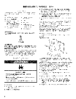
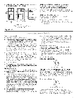
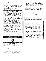
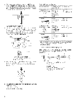
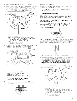
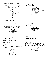
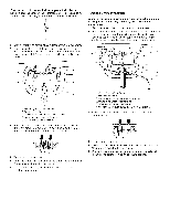
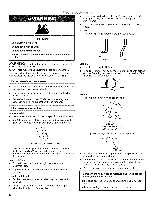
Power Supply Cord i x T _¸_i Direct Wire Fire Hazard Use a new UL listed 30 amp power supply cord. Use a UL listed strain relief. Disconnect power before making electrical connections. Connect neutral wire (white or center wire) to center terminal (silver). Ground wire (green or bare wire) must be connected to green ground connector. Connect remaining 2 supply wires to remaining 2 terminals (gold). Securely tighten all electrical connections. Failure to de so can result in death, fire, or electrical shock. 1. Disconnect power. 2. Remove the hold-down screw and terminal block cover. AB CD Fire Hazard Use 10 gauge solid copper wire. Use a UL listed strain relief. Disconnect power before making electrical connections. Connect neutral wire (white or center wire) to center terminal (silver). Ground wire (green or bare wire) must be connected to green ground connector. Connect remaining 2 supply wires to remaining 2 terminals (gold). Securely tighten all electrical connections. Failure to do so can result in death, fire, or electrical shock. 3. Install strain relief. Style 1: Power supply cord strain relief Remove the screws from a 3/4"(1.9 cm) UL listed strain relief (UL marking on strain relief). Put the tabs of the two clamp sections into the hole below the terminal block opening so that one tab is pointing up and the other is pointing down, and hold in place. Tighten strain relief screws just enough to hold the two clamp sections together• E F A. Terminal block cover B. Hold-down screw C. External ground conductor screw D. Center, silver-colored terminal block screw E. Neutral ground wire F. Hole below terminal block opening A. Strain relief tab pointing up B. Hole below terminal block opening C. Clamp section D. Strain relief tab pointing down
-
 1
1 -
 2
2 -
 3
3 -
 4
4 -
 5
5 -
 6
6 -
 7
7 -
 8
8 -
 9
9 -
 10
10 -
 11
11 -
 12
12 -
13
-
14
-
15
-
16
-
17
-
18
-
19
-
20
-
21
-
22
-
23
-
24
-
25
-
26
-
27
-
28
-
29
-
30
-
31
-
32
-
33
-
34
-
35
-
36
-
37
-
38
-
39
-
40
-
41
-
42
-
43
-
44
-
45
-
46
-
47
-
48
-
49
-
50
-
51
-
52
-
53
-
54
-
55
-
56
-
57
-
58
-
59
-
60
-
61
-
62
-
63
-
64
-
65
-
66
-
67
-
68
-
69
-
70
-
71
-
72
-
73
-
74
-
75
-
76
 |
 |
