Whirlpool WGD92HEF Instruction Sheet
Whirlpool WGD92HEF Manual
 |
View all Whirlpool WGD92HEF manuals
Add to My Manuals
Save this manual to your list of manuals |
Whirlpool WGD92HEF manual content summary:
- Whirlpool WGD92HEF | Instruction Sheet - Page 1
will be 20,000 BTU's per hour, for altitudes up to 10,000 feet (3,048 m). For installations above 2,000 feet (610 m), contact a qualified service agency for derating instructions. NOTE: A qualified service technician is any person or representative of a company who is experienced or trained in - Whirlpool WGD92HEF | Instruction Sheet - Page 2
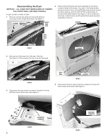
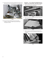
Disassembling the Dryer SECTION 1 - 8.8+ CUBIC FOOT MODELS WITH 29" CABINET, FULL FRONT PANEL, AND REAR CONSOLE To gain access to inside of dryer: 1. Remove console rear plate and rear shelf plate by removing a total of eight (8) screws. See Figure 1. 4. Remove the front panel and door assembly by - Whirlpool WGD92HEF | Instruction Sheet - Page 3
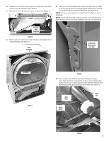
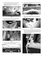
the front bulkhead and lint duct assembly by lifting it off the two (2) front hooks (see Figure 8) and then lowering it to clear the drum support rollers from the drum front. NOTE: Lift up on front of drum to help lift off of rollers on front bulkhead. NOTE: Since the drum - Whirlpool WGD92HEF | Instruction Sheet - Page 4
11. Remove drum from the dryer by grasping the top of the drum belt and front of drum while sliding drum out of cabinet front. SECTION 2 - 7 TO 7.5 CUBIC FOOT MODELS WITH 27" CABINET, FULL FRONT PANEL, AND FRONT CONSOLE 1. Remove dryer top by first removing the two (2) screws from the rear of the - Whirlpool WGD92HEF | Instruction Sheet - Page 5
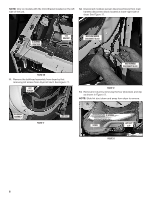
4. Disconnect drum light connector and main console connector as shown in Figure 4. Lift up on console and tilt assembly forward to remove console. NOTE: Only on models with the CCU Bracket located on the left side of the unit. CCU BRACKET MAIN CONSOLE CONNECTOR DRUM LIGHT CONNECTOR 8. Next - Whirlpool WGD92HEF | Instruction Sheet - Page 6
NOTE: Only on models with the CCU Bracket located on the left side of the unit. 12. Disconnect moisture sensor disconnect block from main harness disconnect block located at lower right side of dryer. See Figure 12. (3) SCREWS - RIGHT SIDE CCU BRACKET MOISTURE SENSOR DISCONNECT BLOCK FIGURE 10B - Whirlpool WGD92HEF | Instruction Sheet - Page 7
14. Remove bulkhead assembly by first removing four (4) screws securing the bulkhead assembly to cabinet. Slightly lift up on bulkhead assembly and at the same time pulling away from drum working rollers off drum. See Figure 14. NOTE: During removal of bulkhead, take special notice of the Lower - Whirlpool WGD92HEF | Instruction Sheet - Page 8
18. Remove drum from dryer by grasping the drum belt and front of drum and slide drum out of cabinet front. IMPORTANT: Note position of drum belt, front and rear orientation for reassembly. See Figure 18. NOTE: When removing drum from cabinet be sure not to hit the CCU and bracket assembly knocking - Whirlpool WGD92HEF | Instruction Sheet - Page 9
5. Reach around the back of the drive motor and push the idler wheel arm to relieve the spring tension on the belt; then slide the belt off the idler and motor pulleys. See Figure 4. BELT Determining Gas Valve Style CHANGING THE ORIFICE (BOTH STYLES) 1. Remove the two (2) screws securing the burner - Whirlpool WGD92HEF | Instruction Sheet - Page 10
3. Remove the burner orifice from the gas valve assembly and replace it with the proper orifice furnished in this kit. Orifice number is stamped on one edge of the hex head of orifice. Securely tighten. See Figure 3. Propane gas - Use Orifice No. 55. Butane gas - Use Orifice No. .049. GAS VALVE - Whirlpool WGD92HEF | Instruction Sheet - Page 11
9. Rotate cover dial 25 degrees counterclockwise, lining up "LPG" marking with the indicator on the gas valve. See Figure 8. Pressure Testing (Both Styles) Check minimum and maximum inlet gas pressure: 1. Remove pressure tap plug from valve body using a 3/16" hex wrench. See Figure 1. BEND PLIERS - Whirlpool WGD92HEF | Instruction Sheet - Page 12
4. Turn on and zero manometer. See Figure 4. MANOMETER FRONT PANEL Checking for Leaks 1. With front panel removed, brush or spray an approved non-corrosive leak detection solution onto pressure tap plug. 2. Reassemble dryer in reverse order as described in "Disassembling the Dryer." 3. Turn on gas - Whirlpool WGD92HEF | Instruction Sheet - Page 13
: L'installation de cet ensemble de conversion doit être exécutée par le personnel qualifié d'une agence de service/entretien, conformément aux instructions du fabricant et en conformité avec les prescriptions des codes et règlements applicables publiés par l'autorité juridictionnelle; il - Whirlpool WGD92HEF | Instruction Sheet - Page 14
à tête hexagonale de ¼ po. à l'avant en bas, trois (3) vis à empreinte cruciforme Phillips autour de l'ouverture de la porte et quatre (4) vis Torx T-20 sur le support supérieur du panneau de façade. Voir la Figure 4. Une fois les vis retirées, fermer la porte et lever l'ensemble panneau de fa - Whirlpool WGD92HEF | Instruction Sheet - Page 15
6. Débrancher le connecteur des bandes de détection d'humidité situées dans l'angle inférieur avant droit de la sécheuse. Voir la Figure 6. 7. Retirer les deux (2) vis inférieures du conduit à charpie. Voir la Figure 6. CONDUIT À CHARPIE 9. Retirer l'ensemble cloison avant et conduit à charpie en - Whirlpool WGD92HEF | Instruction Sheet - Page 16
11. Extraire le tambour de la sécheuse en prenant la courroie du tambour par le haut et l'avant du tambour, tout en faisant glisser le tambour hors de la caisse de l'appareil par l'avant. SECTION 2 : MODÈLES DE 7 À 7,5 PIEDS CUBES AVEC CAISSE DE 27 PO, PANNEAU DE FAÇADE PLEINE GRANDEUR ET CONSOLE - Whirlpool WGD92HEF | Instruction Sheet - Page 17
module de la console et faire basculer celui-ci vers l'avant pour la dépose. REMARQUE : Uniquement sur les modèles où le support du MCC est situé à gauche de l'appareil. SUPPORT DU MCC CONNECTEUR PRINCIPAL DE LA CONSOLE 8. Ôter ensuite les trois (3) vis de fixation au sommet du panneau de façade - Whirlpool WGD92HEF | Instruction Sheet - Page 18
REMARQUE : Uniquement sur les modèles où le support du MCC est situé à gauche de l'appareil. (3) VIS - CÔTÉ DROIT BRIDE DU MODULE DE COMMANDE CENTRAL 13. Ôter le conduit d'air chaud de la sécheuse : ôter d' - Whirlpool WGD92HEF | Instruction Sheet - Page 19
séparer le faisceau de câblage du module de la cloison. Voir la Figure 15. REMARQUE : Uniquement sur les modèles où le support du MCC est situé à droit de l'appareil. SUPPORT DU MCC MODULE DE LA CLOISON 16. Pour l'obtention d'un accès approprié au brûleur, il sera nécessaire d'enlever le tambour - Whirlpool WGD92HEF | Instruction Sheet - Page 20
18. Extraire le tambour de la sécheuse : saisir la courroie du tambour et l'avant du tambour, et faire glisser le tambour pour l'extraire par l'avant de la caisse. IMPORTANT : En prévision du remontage, noter la position de la courroie du tambour, et l'orientation à l'avant et à l'arrière. Voir la - Whirlpool WGD92HEF | Instruction Sheet - Page 21
5. Par l'arrière du moteur d'entraînement, pousser le bras de la poulie de tensionnement pour éliminer la tension du ressort sur la courroie; dégager la courroie de la poulie de tensionnement et de la poulie du moteur. Consulter la Figure 4. COURROIE Déterminer le type de l'électrovanne d'admission - Whirlpool WGD92HEF | Instruction Sheet - Page 22
3. Démonter le gicleur du brûleur de l'électrovanne d'admission de gaz, et installer à la place le gicleur approprié fourni dans cet ensemble. Le numéro du gicleur est gravé sur un pan de la tête hexagonale du gicleur. Veiller à bien serrer. Voir Figure 3. Utiliser le gicleur No 55 pour l' - Whirlpool WGD92HEF | Instruction Sheet - Page 23
ÈRE DE RÉGLAGE FIGURE 8 Installation - Liste de contrôle • Vérifier que les deux étiquettes ont été apposées/mises en place conformément aux instructions "Préparation pour l'installation de l'ensemble" - étape 3 et étape 10 ci-dessus. • Dans le cas de la conversion pour l'alimentation au propane - Whirlpool WGD92HEF | Instruction Sheet - Page 24
prise de pression d'une solution de détection des fuites homologuée (non corrosive). 2. Réinstaller les composants de la sécheuse - exécuter les instructions précédentes dans l'ordre inverse, comme décrit dans la section "Démontage de la sécheuse". 3. Ouvrir l'arrivée de gaz. 4. Brancher la sécheuse - Whirlpool WGD92HEF | Instruction Sheet - Page 25
9. Si on observe la formation de bulles, resserrer la connexion qui fait l'objet d'une fuite, et effectuer un nouveau test de recherche des fuites. REMARQUE : Si des bulles se forment sur le conduit d'arrivée de gaz, remplacer le conduit d'arrivée de gaz. 10. Si on n'observe pas la formation de - Whirlpool WGD92HEF | Instruction Sheet - Page 26
26 - Whirlpool WGD92HEF | Instruction Sheet - Page 27
27 - Whirlpool WGD92HEF | Instruction Sheet - Page 28
W10740674A ®/™ © 2014. All rights reserved. ®/™ © 2014. Tous droits réservés. 11/14 Printed in U.S.A. Imprimé aux É.-U.
-
 1
1 -
 2
2 -
 3
3 -
 4
4 -
 5
5 -
 6
6 -
 7
7 -
8
-
9
-
10
-
11
-
12
-
13
-
14
-
15
-
16
-
17
-
18
-
19
-
20
-
21
-
22
-
23
-
24
-
25
-
26
-
27
-
28
 |
 |
W10740674A
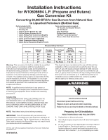
Installation Instructions
for W10606694 L.P. (Propane and Butane)
Gas Conversion Kit
Parts included in Kit:
1 Instruction Sheet
1 Blocking Pin
1 Orifice, Burner-Butane No. .049
1 Orifice, Burner-Propane No. 55
1 Label, Rating Plate Conversion (English)
1 Label, Rating Plate Conversion (French)
1 Label, Conversion Record (English)
1 Label, Conversion Record (French)
1 Label, Burner Baseplate (English/French)
Converting 20,000 BTU/hr Gas Burners from Natural Gas
to Liquefied Petroleum (Bottled Gas)
NOTE:
A qualified service technician is any person or
representative of a company who is experienced or trained
in servicing gas equipment and is familiar with necessary
precautions.
IMPORTANT:
The LP Conversion Kit you received is an
approved kit for converting your gas dryer from natural to LP
propane or butane gas. The kit number shown on the Burner
Data Label located on the Burner Base may not match the kit
you receive due to kit consolidation.
NOTE:
Read these instructions before proceeding.
Canada Only
THIS CONVERSION KIT SHALL BE CARRIED OUT IN
ACCORDANCE WITH THE REQUIREMENTS OF THE
PROVINCIAL AUTHORITIES HAVING JURISDICTION AND
IN ACCORDANCE WITH THE REQUIREMENTS OF THE
CAN-B49.1 AND CAN1-B149.2 INSTALLATION CODE.
Warning:
This conversion kit shall be installed by a qualified
service agency in accordance with the manufacturer’s
instructions and all applicable codes and requirements of
the authority having jurisdiction. The information in these
instructions must be followed to minimize the risk of fire or
explosion or to prevent property damage, personal injury,
or death. The qualified service agency is responsible for the
proper installation of this kit. The installation is not proper
and complete until the operation of the converted appliance
is checked as specified in the manufacturer’s instructions
supplied with this kit.
This dryer has been manufactured for use with Natural Gas.
Installation of this conversion kit converts the dryer for use
with L.P. gas with supply pressure between 8" (203 mm) and
13" (330 mm) water column. If this dryer is converted for use
with L.P. gas by means of this kit, the input rating will be 20,000
BTU’s per hour, for altitudes up to 10,000 feet (3,048 m). For
installations above 2,000 feet (610 m), contact a qualified
service agency for derating instructions.
Preparing for Kit Installation
READ THOROUGHLY AND FOLLOW STEPS
1.
Unplug dryer or disconnect power.
2.
Turn off gas supply using the shut-off valve that supplies
the dryer.
3.
Fill out information on the appropriate Conversion Record
Label (English or French) and apply in a conspicuous
location adjacent to model and serial tag located in the
door well. Go to Section 1, 2, or 3, depending on model.
Tools and Accessories required:
1/4" Socket and Ratchet Wrench
1/4" Nut Driver
5/16" Nut Driver
Phillips-Head Screwdriver
T-20 Torx
®
-head Screwdriver
†
Pliers or Flat-Head Screwdriver
†® Torx and T-20 are registered trademarks of Acument Intellectual
Properties, LLC.
Disassembling the Dryer
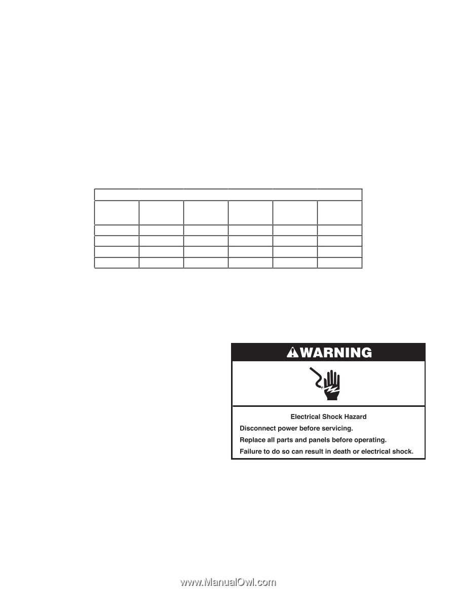
Section
Cabinet
Width
Console
Location
Front Panel
Type
Rated
Capacity
(cubic feet)
Page
1
29"
Rear
Full
8.8+
2
2
27"
Front
Full
7 to 7.5
4
3
29"
Rear
Full
7 to 7.6
8
4
27"
Rear
Toe Panel
7 to 7.5
9