Whirlpool WGD92HEF Instruction Sheet - Page 2
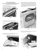
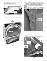
Disassembling the Dryer
 |
View all Whirlpool WGD92HEF manuals
Add to My Manuals
Save this manual to your list of manuals |
Page 2 highlights
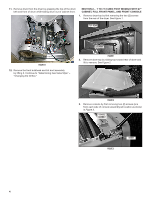
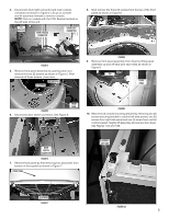
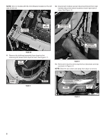
Disassembling the Dryer SECTION 1 - 8.8+ CUBIC FOOT MODELS WITH 29" CABINET, FULL FRONT PANEL, AND REAR CONSOLE To gain access to inside of dryer: 1. Remove console rear plate and rear shelf plate by removing a total of eight (8) screws. See Figure 1. 4. Remove the front panel and door assembly by removing a total of eleven (11) screws: Four (4) ¼" hex-head screws along the bottom front, three (3) Phillips-head screws around the door opening, and four (4) T-20 Torx-head screws on the top front panel bracket. See Figure 4. Once screws are removed, close the door and lift up the front panel and door assembly to remove. (5) SCREWS CONSOLE REAR PLATE (4) SCREWS REAR SHELF PLATE (3) SCREWS FIGURE 1 2. Remove two (2) screws from the rear of the top. See Figure 2. This will allow the top to be slid rearward. TOP (3) SCREWS (2) SCREWS FIGURE 2 3. Disconnect the door switch connector located in the top left front corner of the dryer. See Figure 3. FRONT PANEL (4) SCREWS FIGURE 4 5. Disconnect the drum light connector located in the top left front corner of the dryer. See Figure 5. DOOR SWITCH CONNECTOR FIGURE 3 2 DRUM LIGHT CONNECTOR FIGURE 5
-
 1
1 -
 2
2 -
 3
3 -
 4
4 -
 5
5 -
 6
6 -
 7
7 -
 8
8 -
9
-
10
-
11
-
12
-
13
-
14
-
15
-
16
-
17
-
18
-
19
-
20
-
21
-
22
-
23
-
24
-
25
-
26
-
27
-
28
 |
 |
