Whirlpool WGD92HEF Instruction Sheet - Page 5
Switch, Connector, Screws, Front, Panel, Dryer Door, Main Console, Screws, Front Panel, Drum Light,
 |
View all Whirlpool WGD92HEF manuals
Add to My Manuals
Save this manual to your list of manuals |
Page 5 highlights
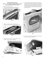
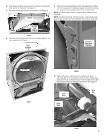
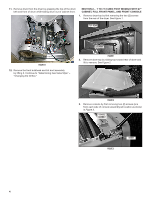
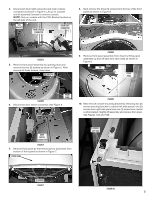
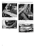
4. Disconnect drum light connector and main console connector as shown in Figure 4. Lift up on console and tilt assembly forward to remove console. NOTE: Only on models with the CCU Bracket located on the left side of the unit. CCU BRACKET MAIN CONSOLE CONNECTOR DRUM LIGHT CONNECTOR 8. Next remove the three (3) screws from the top of the front panel as shown in Figure 8. (3) SCREWS FIGURE 4 5. Remove front panel assembly by opening door and remove the two (2) screws as shown in Figure 5. After removal of these screws, close door. DRYER DOOR (2) SCREWS FIGURE 8 9. Remove front panel assembly from dryer by lifting panel assembly up and off tabs (one each side) as shown in Figure 9. TAB FRONT PANEL FRONT PANEL FIGURE 5 6. Disconnect door switch connector. See Figure 6. FIGURE 9 10. Next remove console mounting bracket by removing two (2) screws securing bracket to cabinet left side panels, two (2) screws from right side panel and one (1) screw from central control bracket. Slightly lift assembly and remove from dryer. See Figures 10A and 10B. DOOR SWITCH CONNECTOR FIGURE 6 7. Remove front panel by first removing four (4) screws from bottom of front panel as shown in Figure 7. FRONT PANEL (2) SCREWS LEFT SIDE (4) SCREWS FIGURE 7 FIGURE 10A 5
-
 1
1 -
 2
2 -
 3
3 -
 4
4 -
 5
5 -
 6
6 -
 7
7 -
 8
8 -
 9
9 -
 10
10 -
 11
11 -
12
-
13
-
14
-
15
-
16
-
17
-
18
-
19
-
20
-
21
-
22
-
23
-
24
-
25
-
26
-
27
-
28
 |
 |
