Whirlpool WGD92HEF Instruction Sheet - Page 8
To 7.6 Cubic Foot Models With 29
 |
View all Whirlpool WGD92HEF manuals
Add to My Manuals
Save this manual to your list of manuals |
Page 8 highlights
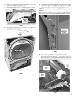
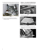
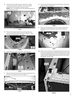
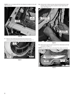
18. Remove drum from dryer by grasping the drum belt and front of drum and slide drum out of cabinet front. IMPORTANT: Note position of drum belt, front and rear orientation for reassembly. See Figure 18. NOTE: When removing drum from cabinet be sure not to hit the CCU and bracket assembly knocking it from its hanging position. Continue to "Determining Gas Valve Style" - "Changing the Orifice." 2. Remove two (2) hex head screws from the cabinet front panel. See Figure 2. DOOR SWITCH CONNECTOR REAR FRONT DRUM BELT CABINET FRONT SCREW FIGURE 2 3. Disconnect the door switch connector from the harness connector. See Figure 2. 4. Lift the front panel, unhook it from the bottom two hangers and remove the panel. See Figure 3. FIGURE 18 SECTION 3 - 7 TO 7.6 CUBIC FOOT MODELS WITH 29" CABINET, FULL FRONT PANEL, AND REAR CONSOLE 1. Lift dryer top. Use a putty knife to press against the left and right spring clips to release them from the top. Gently lean dryer top toward the wall so as not to damage the dryer top or wall. See Figure 1. SPRING CLIPS FIGURE 1 HANGER FIGURE 3 FRONT PANEL 8
-
 1
1 -
2
-
 3
3 -
 4
4 -
 5
5 -
 6
6 -
 7
7 -
 8
8 -
 9
9 -
 10
10 -
 11
11 -
 12
12 -
 13
13 -
14
-
15
-
16
-
17
-
18
-
19
-
20
-
21
-
22
-
23
-
24
-
25
-
26
-
27
-
28
 |
 |
