Whirlpool WRT138FFD Installation Instructions
Whirlpool WRT138FFD Manual
 |
View all Whirlpool WRT138FFD manuals
Add to My Manuals
Save this manual to your list of manuals |
Whirlpool WRT138FFD manual content summary:
- Whirlpool WRT138FFD | Installation Instructions - Page 1
Installation G U I D E 2181913E MODULAR ICE MAKER KIT www.whirlpool.com - Whirlpool WRT138FFD | Installation Instructions - Page 2
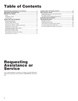
the copper tubing 19 Connecting the power/leveling the unit 20 STARTING THE ICE MAKER 21 TROUBLESHOOTING 22 Operational notes 22 Troubleshooting chart 22 The modular ice maker service sheet 23 Ice maker replacement parts list 24 Ice maker replacement parts list (cont'd 25 Requesting - Whirlpool WRT138FFD | Installation Instructions - Page 3
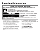
Guide. Read it carefully so you are familiar with it. Your safety and the safety of others are very important. We have provided many important safety messages in this manual can happen if the instructions are not followed. ‡ This Installation Guide gives you complete instructions on how to install - Whirlpool WRT138FFD | Installation Instructions - Page 4
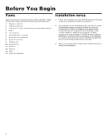
13. Ruler 14. Step stool (optional) Installation notes 1. Follow the instructions carefully. Read through the entire step so that you understand it before you perform it. 2. The illustrations in this Installation Guide are meant to clarify the installation steps you need to perform. - Whirlpool WRT138FFD | Installation Instructions - Page 5
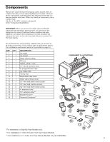
Components Remove the contents from the shipping carton and set them on a table where they can be easily identified and located. Check all of the components in the kit against the following list to help you become familiar with them. When you identify a component, place a check mark ( 3) after it. - Whirlpool WRT138FFD | Installation Instructions - Page 6
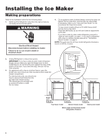
the wire ice cube holder (if necessary, refer to your "Use and Care Guide" for the procedure). Set these items aside. On top-mount models without a ice tray shelf. Place the shelf aside, as you will use it later to support the ice bucket. If you have a side-by-side model refrigerator, proceed to - Whirlpool WRT138FFD | Installation Instructions - Page 7
Side-by-side models Refer to the side diagram for the following steps. You will be working inside the freezer compartment. 1. Remove the phillips screw from the ice maker wiring cover and remove the cover. 2. Refer to DETAIL A, and with a pair of pliers, break away the tabs from the wiring cover and - Whirlpool WRT138FFD | Installation Instructions - Page 8
Refer to the side diagram for the following step. You will be working inside the freezer compartment. 1. Install the plastic extension by sliding it over the fill tube as far as it will go. Refer back to the side diagram for the following step. 2. Position the wiring harness so that it is through - Whirlpool WRT138FFD | Installation Instructions - Page 9
Top/bottom freezer models Refer to the side diagrams for the following 2 steps. You will be working inside the freezer compartment. 1. On models with a open-top ice maker fill tube and wiring cover: Remove the screw from the ice maker wiring cover. Squeeze top and bottom to loosen snaps. Remove and - Whirlpool WRT138FFD | Installation Instructions - Page 10
Top/bottom freezer models (continued) Refer to the side diagrams for the following steps. 1. (continued) On 14 to 18 Cubic Foot Top Freezer and Bottom Freezer Models Locate the fill tube and the round foam gasket from the ice maker kit (the gasket may already be installed on the fill tube). If not - Whirlpool WRT138FFD | Installation Instructions - Page 11
Installing the tubing clips Refer to the side diagram for the following steps. 1. Remove the seven hex-head screws from the rear access cover, then remove the cover and set it aside. NOTE: If you have a later unit with a metal panel, (see DETAIL A), remove the hex-head screw from the access cover. - Whirlpool WRT138FFD | Installation Instructions - Page 12
Preparing the water valve tubing (for bottom freezers only) Refer to the side diagram for the following steps. 1. Remove the tape from coiled flexible tubing coming from the water valve and straighten it. CUT TUBING HERE 2. Starting at the top of the compression nut on the water valve, measure - Whirlpool WRT138FFD | Installation Instructions - Page 13
Mounting the water valve Refer to the diagram below for the following steps. NOTE: For 11 Cubic Foot Top Freezer Models only, use a wire tie to get together capillary tube and dryer. This should be done by installer before installing water valve, to make more room for water valve installation. - Whirlpool WRT138FFD | Installation Instructions - Page 14
Connecting the water valve tubing Refer to the diagram below for the following steps. 1. Refer to the inset in DETAIL A and pull the plastic insert out of the fill tube spout and discard it. 2. Locate the water valve tubing clamp (from the ice maker kit), and note that one of the flanges is made - Whirlpool WRT138FFD | Installation Instructions - Page 15
Mounting the ice maker Refer to the side diagram for the following step. 1. Look at the ice maker's fill cup and note that the rear of the cup has a "U" shaped groove (either of the sides may also be grooved). Use your fingers, (or a pair of pliers, if it is easier), and remove only the rear "knock- - Whirlpool WRT138FFD | Installation Instructions - Page 16
Refer to the side diagrams for the following steps. 1. Position the ice maker inside the freezer compartment and connect its wiring connector to the wiring harness connector so they lock together (the locking arm will snap over the raised tab). The connectors will fit together only one way. 2. For - Whirlpool WRT138FFD | Installation Instructions - Page 17
Connecting the Water Supply Read all directions before you begin. IMPORTANT: Connect to potable water supply only. Do not use with water that is microbiologically unsafe or of unknown quality without adequate disinfection before or after the system. Systems certified for cyst reduction may be used - Whirlpool WRT138FFD | Installation Instructions - Page 18
a coil of copper tubing to allow the refrigerator to be pulled out of the cabinet or away from the wall for service. Connect to Refrigerator Follow the connection instructions specific to your model. 1. Remove plastic cap from water valve inlet port. Attach the copper tubing to the valve inlet using - Whirlpool WRT138FFD | Installation Instructions - Page 19
Final Installation Installing the access cover and forming the copper tubing 1. Reinstall the rear access cover on the refrigerator so the water valve tubing is inside the cover, and the copper water line is outside (see the diagram below), then secure the cover with the seven hex-head screws you - Whirlpool WRT138FFD | Installation Instructions - Page 20
use an adapter. Do not use an extension cord. Failure to follow these instructions can result in death, fire, or electrical shock. 1. Plug the power cord adjust the front casters, as outlined in your refrigerator's "Use and Care Guide." 3. Check the position of the ice maker. If it is crooked and - Whirlpool WRT138FFD | Installation Instructions - Page 21
this happens, make two or three batches of ice and discard them. After that, the "off-taste" should be gone. If you have any problems, refer to "Troubleshooting" on page 22. This completes the installation of your Ice Maker. Installing the ice bucket DETAIL A Tabs Slots Raise arm to stop ice Off - Whirlpool WRT138FFD | Installation Instructions - Page 22
local appliance dealer. Troubleshooting chart The following chart lists several common problems that could occur with your Ice Maker. PROBLEM One or more arm to the "off" position (see page 21); then contact your local service center. It will take 48 hours to fill the ice bucket. The ice maker - Whirlpool WRT138FFD | Installation Instructions - Page 23
The modular ice maker service sheet Module Test Points N M Removal screws (3) V L H T TEST POINTS L-H L-M MODULE OHMMETER CHECKS (NO POWER TO ICE MAKER AND EJECTOR BLADES IN PARK) COMPONENT MODULE POSITION MOLD HEATER ATTACHED TO SUPPORT MOTOR DISCONNECT FROM SUPPORT OHMS 72 8800 - Whirlpool WRT138FFD | Installation Instructions - Page 24
628256 2155021 489128 1115846 628366 627929 1115844 628229 628379 Description Mold and Heater Assembly Bearing and Inlet Ejector Ice Stripper Support Retainer, Thermostat (2) Thermostat (also Order #542369 Cement Alumilastic) Screw, (2) 10-32 x 49/64" Module, Assembly Motor Screw, (2) 3-24 x 23/64 - Whirlpool WRT138FFD | Installation Instructions - Page 25
x 1/2" Screw, 8-32 x 1/2" Insert, Plastic Tube Tube Assembly, Inlet Valve Nut, Inlet Valve Washer Dampener Tube Clamp Tube Clamp Tube Clamp Clamp, Service Cord Plastic Tube Nut and Sleeve Assembly Insert, Plastic Tube Accessory Bag, Inside Screw, 8 x 1/2" Tube, Water Inlet Wiring Assembly, Ice Maker - Whirlpool WRT138FFD | Installation Instructions - Page 26
G U I D E d'installation MACHINE À GLAÇONS MODULAIRE (ENSEMBLE) www.whirlpool.com 26 - Whirlpool WRT138FFD | Installation Instructions - Page 27
Table des matières DEMANDE D'ASSISTANCE OU DE DÉPANNAGE 27 INFORMATION IMPORTANTE 28 AVANT DE COMMENCER 29 Outillage necessaire 29 Notes concernant l'installation 29 Composants 30 INSTALLATION DE LA MACHINE À GLAÇONS 31 Opérations préparatoires 31 Modèle à compartiments juxtaposés 32 Modè - Whirlpool WRT138FFD | Installation Instructions - Page 28
est le danger potentiel et vous disent comment réduire le risque de blessure et ce qui peut se produire en cas de non-respect des instructions. ‡ Ce Guide d'installation présente les instructions complètes d'installation de la machine à glaçons dans le congélateur du réfrigérateur, et les - Whirlpool WRT138FFD | Installation Instructions - Page 29
gle 14. Tabouret (option) Notes concernant l'installation 1. Exécuter les instructions exactement telles qu'elles sont décrites; lire la totalité de la avant de l'exécuter. 2. Les illustrations présentées dans ce Guide d'installation clarifient la description des étapes de l'installation à exécuter. - Whirlpool WRT138FFD | Installation Instructions - Page 30
de tôlerie/tête hexagonale de 1⁄2" Vis à métaux/tête hexagonale de 1⁄2" Vis de tôlerie/tête hexagonale de 3⁄4" Tube d'extension de 4" ** Tube d'extension de 3 3⁄8"*** Bride de support du tube de remplissage*** Condenseur à oeillet** ILLUSTRATION DES COMPOSANTS 11 12 14 13 15 16 17 18 30 - Whirlpool WRT138FFD | Installation Instructions - Page 31
glaçons. Le non-respect de cette instruction peut causer un décès ou un choc électrique retenue des glaçons (si nécessaire, consulter le "Guide d'utilisation et d'entretien" au sujet du processus); conserver tagère à part; elle sera réutilisée comme support du panier à glaçons. Pour un appareil à - Whirlpool WRT138FFD | Installation Instructions - Page 32
Modèle à compartiments juxtaposés Voir le diagramme adjacent au sujet des étapes suivantes. Il sera nécessaire de travailler à l'intérieur du compartiment de congélation. 1. Ôter la vis Phillips qui retient le couvercle du logement du câblage de la machine à glaçons, et ôter le couvercle. 2. Voir - Whirlpool WRT138FFD | Installation Instructions - Page 33
Voir le diagramme adjacent au sujet de l'étape suivante. Il sera nécessaire de travailler à l'intérieur du compartiment de congélation. 1. Installer l'extension de plastique - faire glisser le composant d'extension sur le tube de remplissage, aussi loin qu'il peut aller. Ouverture de passage du câ - Whirlpool WRT138FFD | Installation Instructions - Page 34
élateur en haut, de 11 pi³ (ensemble 24ECKMF) Installer la "bride de support du tube de remplissage" sur la paroi arrière du réfrigérateur; utiliser érer le tube de remplissage à travers le trou de la "bride de support du tube de remplissage" avec bec verseur; effectuer un mouvement de torsion pour - Whirlpool WRT138FFD | Installation Instructions - Page 35
Modèle à compartiments superposés (suite) Voir les diagrammes adjacents au sujet des étapes suivantes. 3. (suite) Modèle à congélateur en haut et modèle à congélateur en bas (de 14 à 18 pi³) Dans l'ensemble de machine à glaçons, identifier le tube de remplissage et le joint de mousse rond (le joint - Whirlpool WRT138FFD | Installation Instructions - Page 36
une autre configuration du tube de remplissage (pour un modèle de 11 pi³ à congélateur en haut, avec tube de remplissage et bride de support du tube de remplissage). Pour un modèle à congélateur en bas, passer à la page 37. Pour un appareil à compartiments juxtaposés ou un modèle - Whirlpool WRT138FFD | Installation Instructions - Page 37
Préparation du tube de l'électrovanne d'admission d'eau (seulement pour un modèle à congélateur en bas) Voir le diagramme adjacent au sujet des étapes suivantes. 1. Enlever le ruban du tube souple en spirale provenant du robinet, puis redresser ce dernier. COUPER LE TUBE MALLÉABLE ICI 2. Depuis - Whirlpool WRT138FFD | Installation Instructions - Page 38
Montage de l'électrovanne d'admission d'eau Voir le diagramme ci-dessous au sujet des étapes suivantes. REMARQUE : Seulement pour un modèle de 11 pi³ à congélateur en haut, utiliser une attache de câblage pour assujettir ensemble le tube capillaire et le module d'assèchement. L'installateur devrait - Whirlpool WRT138FFD | Installation Instructions - Page 39
le tube Bec verseur malléable dans du tube de le bec verseur aussi remplissage loin que c'est possible DÉTAIL D Tube de remplissage Bride de support du tube de remplissage Serrer la bride avec la vis sur le bec verseur autant que c'est possible Enfiler la bride sur le bec - Whirlpool WRT138FFD | Installation Instructions - Page 40
Mounting the ice maker Voir le diagramme adjacent au sujet de l'étape suivante. 1. Examiner la coupelle de remplissage de la machine à glaçons; noter la rainure en "U" à l'arrière (il peut également y avoir des rainures sur un côté ou l'autre). À la force des doigts (ou utiliser une pince si c'est - Whirlpool WRT138FFD | Installation Instructions - Page 41
Voir les diagrammes adjacents au sujet des étapes suivantes. 1. Positionner la machine à glaçons à l'intérieur du compartiment de congélation, et raccorder/verrouiller ensemble son connecteur de câblage et le connecteur de la tresse de câblage (la patte de blocage se calera audessus de l'onglet de - Whirlpool WRT138FFD | Installation Instructions - Page 42
Dernières étapes de l'installation Installation du couvercle de l'ouverture d'accès et formage du tube de cuivre malléable 1. Réinstaller le couvercle de l'ouverture d'accès arrière sur le réfrigérateur - il faudra que le tube de l'électrovanne d'admission d'eau soit à l'intérieur sous le - Whirlpool WRT138FFD | Installation Instructions - Page 43
Raccordement à la conduite d'eau Lire toutes les instructions avant de commencer. IMPORTANT : ‡ Brancher sur une alimentation en eau potable uniquement. 3. Utiliser un robinet d'arrêt quart de tour ou équivalent alimenté par une conduite d' - Whirlpool WRT138FFD | Installation Instructions - Page 44
ou du mur en cas de dépannage. Raccordement au réfrigérateur Suivre les instructions relatives au modèle utilisé pour le raccordement. 1. Ôter le bouchon de raccordement en tirant sur le tube en cuivre. 2. Créer une boucle de service avec le tube en cuivre. Éviter de déformer le tube en cuivre en - Whirlpool WRT138FFD | Installation Instructions - Page 45
pas utiliser un câble de rallonge. Le non-respect de ces instructions peut causer un décès, un incendie ou un choc électrique. 1. rateur, employer le processus de réglage des roulettes avant, décrit dans le "Guide d'utilisation et d'entretien du réfrigérateur". 3. Contrôler la position de - Whirlpool WRT138FFD | Installation Instructions - Page 46
Mise en marche de la machine à glaçons 1. Laver le panier à glaçons, et faire glisser le panier sous la machine à glaçons (voir le diagramme adjacent) aussi loin qu'il peut aller. Le panier à glaçons reposera sur le sommet de l'étagère du congélateur. IMPORTANT : Dans le cas d'un appareil à congé - Whirlpool WRT138FFD | Installation Instructions - Page 47
des deux éléments de filtrage, fermer l'arrivée d'eau et démonter l'électrovanne d'admission d'eau (ce travail peut être confié à un centre de service après-vente local). Si la qualité de l'eau distribuée localement nécessite l'exécution d'un nettoyage périodique, ou si l'eau utilisée provient d'un - Whirlpool WRT138FFD | Installation Instructions - Page 48
BOÎTER LE COUVERCLE. FAIRE TOURNER LE BOUTON (INDEXAGE) ET RÉINSTALLER À LA MÊME POSITION POUR LE REMPLISSAGE D'EAU. MODULE, MOTEUR ET ENSEMBLE DE SUPPORT INSÉRER UN TOURNEVIS PHILLIPS DANS LES OUVERTURES D'ACCÈS DU MODULE. DESSERRER LES DEUX VIS. DÉCONNECTER LE BRAS DE COMMANDE. DÉTACHER LE MOULE - Whirlpool WRT138FFD | Installation Instructions - Page 49
489128 1115846 628366 627929 1115844 628229 628379 Moule et élément chauffant (ensemble) Palier et entrée Éjecteur Dispositif d'expulsion des glaçons Support Pièce de retenue pour thermostat (2) Thermostat (commander également l'article no 542369, adhésif alumilastique) Vis (2), 10-32 x 49/64 - Whirlpool WRT138FFD | Installation Instructions - Page 50
lectrovanne Rondelle Amortisseur Bride de fixation pour tube Bride de fixation pour tube Bride de fixation pour tube Bride pour cordon d'alimentation (service) Tube de plastique Écrou et virole (ensemble) Élément inséré en plastique, pour tube Sac d'accessoires (intérieur) Vis no 8 x 1/2"" Tube pour - Whirlpool WRT138FFD | Installation Instructions - Page 51
NOTES 51 - Whirlpool WRT138FFD | Installation Instructions - Page 52
NOTES 52 - Whirlpool WRT138FFD | Installation Instructions - Page 53
NOTES 53 - Whirlpool WRT138FFD | Installation Instructions - Page 54
NOTES 54 - Whirlpool WRT138FFD | Installation Instructions - Page 55
NOTES 55 - Whirlpool WRT138FFD | Installation Instructions - Page 56
2181913E ®/™ ©2021 Whirlpool. All rights reserved. Tous droits réservés. 10/21
-
 1
1 -
 2
2 -
 3
3 -
 4
4 -
 5
5 -
 6
6 -
 7
7 -
8
-
9
-
10
-
11
-
12
-
13
-
14
-
15
-
16
-
17
-
18
-
19
-
20
-
21
-
22
-
23
-
24
-
25
-
26
-
27
-
28
-
29
-
30
-
31
-
32
-
33
-
34
-
35
-
36
-
37
-
38
-
39
-
40
-
41
-
42
-
43
-
44
-
45
-
46
-
47
-
48
-
49
-
50
-
51
-
52
-
53
-
54
-
55
-
56
 |
 |
www.whirlpool.com
Installation
G
U
I
D
E
MODULAR ICE MAKER KIT
2181913E