Yamaha DM2000 Owner's Manual - Page 138
Viewing Channel Parameter Settings, set: Comp On/Off, Threshold, Ratio, Attack, Release, Gain
 |
View all Yamaha DM2000 manuals
Add to My Manuals
Save this manual to your list of manuals |
Page 138 highlights
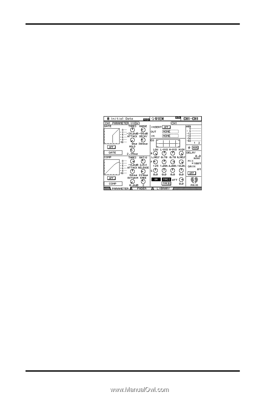
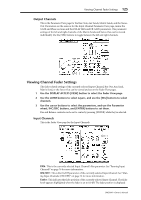
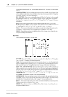
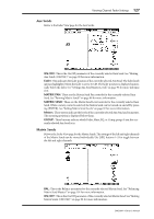
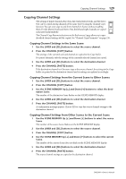
124 Chapter 12-Common Channel Functions Viewing Channel Parameter Settings The parameter setting of the currently selected Input Channel, Bus Out, Aux Send, Matrix Send, or the Stereo Out can be viewed and set on the Parameter View pages. 1 Use the DISPLAY ACCESS [VIEW] button to select the Parameter View page. 2 Use the LAYER buttons to select Layers, and use the [SEL] buttons to select channels. 3 Use the cursor buttons to select the parameters, and use the Parameter wheel, INC/DEC buttons, and [ENTER] buttons to set them. Input Channels This is the Parameter View page for the Input Channels. GATE: The following Gate parameters for the currently selected Input Channel can be set: Gate On/Off, Threshold, Range, Attack, Decay, and Hold. The GR meter indicates the amount of gain reduction being applied by the Gate. Also displayed are the gate curve and gate type. See "Gating Input Channels" on page 69 for more information. COMP: The following Compressor parameters for the currently selected channel can be set: Comp On/Off, Threshold, Ratio, Attack, Release, Gain, and Knee. The GR meter indicates the amount of gain reduction being applied by the Compressor. Also displayed are the comp curve and comp type. See "Compressing Channels" on page 113 for more information. INSERT: The currently selected channel's Insert can be turned on and off and patched. See "Using Inserts" on page 111 for more information. EQ: The currently selected channel's EQ and Attenuator can be set. Also displayed is the EQ curve of the currently selected Input Channel. See "Using EQ" on page 107 for more information. Meters: These meters indicate the levels of the currently selected channel and its horizontal or vertical partner. Phase: The signal phase of the currently selected Input Channel can be reversed. See "Reversing the Signal Phase" on page 68 for more information. DELAY: The currently selected channel's Delay function can be set. See "Delaying Channel Signals" on page 117 for more information. PAIR: This heart icon indicates whether or not channels are paired. See "Pairing Channels" on page 120 for more information. DM2000-Owner's Manual
-
 1
1 -
2
-
3
-
4
-
5
-
6
-
7
-
8
-
9
-
10
-
11
-
12
-
13
-
14
-
15
-
16
-
17
-
18
-
19
-
20
-
21
-
22
-
23
-
24
-
25
-
26
-
27
-
28
-
29
-
30
-
31
-
32
-
33
-
34
-
35
-
36
-
37
-
38
-
39
-
40
-
41
-
42
-
43
-
44
-
45
-
46
-
47
-
48
-
49
-
50
-
51
-
52
-
53
-
54
-
55
-
56
-
57
-
58
-
59
-
60
-
61
-
62
-
63
-
64
-
65
-
66
-
67
-
68
-
69
-
70
-
71
-
72
-
73
-
74
-
75
-
76
-
77
-
78
-
79
-
80
-
81
-
82
-
83
-
84
-
85
-
86
-
87
-
88
-
89
-
90
-
91
-
92
-
93
-
94
-
95
-
96
-
97
-
98
-
99
-
100
-
101
-
102
-
103
-
104
-
105
-
106
-
107
-
108
-
109
-
110
-
111
-
112
-
113
-
114
-
115
-
116
-
117
-
118
-
119
-
120
-
121
-
122
-
123
-
124
-
125
-
126
-
127
-
128
-
129
-
130
-
131
-
132
-
 133
133 -
 134
134 -
 135
135 -
 136
136 -
 137
137 -
 138
138 -
 139
139 -
 140
140 -
 141
141 -
 142
142 -
 143
143 -
144
-
145
-
146
-
147
-
148
-
149
-
150
-
151
-
152
-
153
-
154
-
155
-
156
-
157
-
158
-
159
-
160
-
161
-
162
-
163
-
164
-
165
-
166
-
167
-
168
-
169
-
170
-
171
-
172
-
173
-
174
-
175
-
176
-
177
-
178
-
179
-
180
-
181
-
182
-
183
-
184
-
185
-
186
-
187
-
188
-
189
-
190
-
191
-
192
-
193
-
194
-
195
-
196
-
197
-
198
-
199
-
200
-
201
-
202
-
203
-
204
-
205
-
206
-
207
-
208
-
209
-
210
-
211
-
212
-
213
-
214
-
215
-
216
-
217
-
218
-
219
-
220
-
221
-
222
-
223
-
224
-
225
-
226
-
227
-
228
-
229
-
230
-
231
-
232
-
233
-
234
-
235
-
236
-
237
-
238
-
239
-
240
-
241
-
242
-
243
-
244
-
245
-
246
-
247
-
248
-
249
-
250
-
251
-
252
-
253
-
254
-
255
-
256
-
257
-
258
-
259
-
260
-
261
-
262
-
263
-
264
-
265
-
266
-
267
-
268
-
269
-
270
-
271
-
272
-
273
-
274
-
275
-
276
-
277
-
278
-
279
-
280
-
281
-
282
-
283
-
284
-
285
-
286
-
287
-
288
-
289
-
290
-
291
-
292
-
293
-
294
-
295
-
296
-
297
-
298
-
299
-
300
-
301
-
302
-
303
-
304
-
305
-
306
-
307
-
308
-
309
-
310
-
311
-
312
-
313
-
314
-
315
-
316
-
317
-
318
-
319
-
320
-
321
-
322
-
323
-
324
-
325
-
326
-
327
-
328
-
329
-
330
-
331
-
332
-
333
-
334
-
335
-
336
-
337
-
338
-
339
-
340
-
341
-
342
-
343
-
344
-
345
-
346
-
347
-
348
-
349
-
350
-
351
-
352
-
353
-
354
-
355
-
356
-
357
-
358
-
359
-
360
-
361
-
362
 |
 |