Yamaha HTR-5440 Owner's Manual - Page 30
TUNING, Connecting the Antennas
 |
View all Yamaha HTR-5440 manuals
Add to My Manuals
Save this manual to your list of manuals |
Page 30 highlights
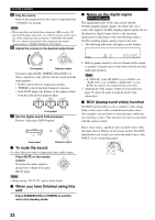
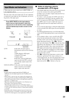
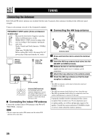
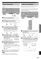
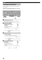
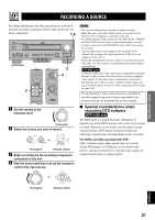
TUNING Connecting the Antennas Both AM and FM indoor antennas are included with this unit. In general, these antennas should provide sufficient signal strength. Connect each antenna correctly to the designated terminals. FREQUENCY STEP switch (China and General models only) FREQUENCY STEP Because the interstation frequency spacing differs in different areas, set the 50KHZ /9KHZ FREQUENCY STEP switch (locating at the 100KHZ /10KHZ FM/AM rear) according to the frequency spacing in your area. North, Central and South America: 100 kHz/ 10 kHz Other area: 50 kHz/9 kHz Before setting this switch, disconnect the AC power plug of this unit from the AC outlet. AM loop antenna (included) Indoor FM antenna (included) AM ANT GND FM ANT TUNER 75 UNBAL. (U.S.A. model) Ground (GND terminal) For maximum safety and minimum interference, connect the antenna GND terminal to a good earth ground. A good earth ground is a metal stake driven into moist earth. I Connecting the indoor FM antenna Connect the included indoor FM antenna to the FM ANT 75Ω UNBAL. terminal. Note • Do not connect an outdoor FM antenna and the indoor FM antenna at the same time. I Connecting the AM loop antenna 31 4 25 Antenna stand 1 Press and hold the tab to unlock the terminal hole. 2 Insert the AM loop antenna lead wires into the AM ANT and GND terminals. 3 Release the tab to lock the lead wires. Lightly pull the lead wires to confirm a good connection. 4 Attach the loop antenna to the antenna stand. 5 Orient the AM loop antenna so that the best reception is obtained. y • The AM loop antenna can be removed from the stand and attached to a wall, etc. Notes • The AM loop antenna should be placed away from this unit. • The AM loop antenna should always be connected, even if an outdoor AM antenna is connected to this unit. A properly installed outdoor antenna provides clearer reception than an indoor one. If you experience poor reception quality, an outdoor antenna may improve the quality. Consult the nearest authorized YAMAHA dealer or service center about the outdoor antennas. 26
-
 1
1 -
2
-
3
-
4
-
5
-
6
-
7
-
8
-
9
-
10
-
11
-
12
-
13
-
14
-
15
-
16
-
17
-
18
-
19
-
20
-
21
-
22
-
23
-
24
-
 25
25 -
 26
26 -
 27
27 -
 28
28 -
 29
29 -
 30
30 -
 31
31 -
 32
32 -
 33
33 -
 34
34 -
 35
35 -
36
-
37
-
38
-
39
-
40
-
41
-
42
-
43
-
44
-
45
-
46
-
47
-
48
-
49
-
50
-
51
-
52
-
53
-
54
-
55
-
56
-
57
-
58
-
59
-
60
-
61
-
62
-
63
-
64
-
65
-
66
-
67
-
68
-
69
 |
 |