Yamaha MX-A5200 MX-A5200 Owner s Manual
Yamaha MX-A5200 Manual
 |
View all Yamaha MX-A5200 manuals
Add to My Manuals
Save this manual to your list of manuals |
Yamaha MX-A5200 manual content summary:
- Yamaha MX-A5200 | MX-A5200 Owner s Manual - Page 1
Power Amplifier/Ampli de Puissance Owner's Manual Mode d'emploi Manual de Instrucciones Manual do Proprietário English Français Español Português - Yamaha MX-A5200 | MX-A5200 Owner s Manual - Page 2
- Yamaha MX-A5200 | MX-A5200 Owner s Manual - Page 3
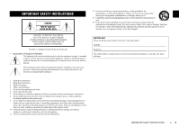
operating and maintenance (servicing) instructions in the literature accompanying instructions. 8 Do not install near any heat sources such as radiators, heat registers, stoves, or other apparatus (including amplifiers the obsolete outlet. 10 Protect the power cord from being walked on or pinched - Yamaha MX-A5200 | MX-A5200 Owner s Manual - Page 4
according to the instructions found in the users manual, may cause interference "ON", please try to eliminate the problem by using one of the following measures: Relocate either Yamaha Corporation of America 6600 Orangethorpe Avenue, Buena Park, CA 90620 714-522-9011 Power Amplifier MX-A5200 - Yamaha MX-A5200 | MX-A5200 Owner s Manual - Page 5
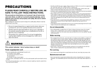
unit properly and safely. Be sure to follow these instructions. After reading this manual, be sure to keep it in a safe place power immediately and unplug the power cord from the AC outlet. Then, request an inspection from the dealer where you purchased the unit or from qualified Yamaha service - Yamaha MX-A5200 | MX-A5200 Owner s Manual - Page 6
the power and disconnect the power plug. If any of the following abnormalities occur, immediately turn off any amplifiers and receivers. - The power cord Yamaha service personnel. CAUTION This content indicates "risk of injury." Power supply/power cord • Do not use an AC outlet where the power - Yamaha MX-A5200 | MX-A5200 Owner s Manual - Page 7
in the unit, leave the unit for several hours without turning on the power until it is completely dry before use. Using the unit while there is condensation manual • The illustrations and screens in this manual are for instructional purposes only. • The company names and product names in this manual - Yamaha MX-A5200 | MX-A5200 Owner s Manual - Page 8
shock. Be careful with short circuits. DO NOT TOUCH! (when the unit is powered on) 20 cm (7-7/8") or more The unit does not have volume controls. Make sure you connect a device with volume control (such as a pre-amplifier) to the unit. If you connect a device without volume control (such as a CD - Yamaha MX-A5200 | MX-A5200 Owner s Manual - Page 9
20 Using three speakers for one channel (multi-speaker 20 Appendix 21 Input-output signal path diagram 21 Troubleshooting 22 Specifications 23 Accessories Check that the following accessories are supplied with the product. Power cable *The supplied power cable varies depending on the region - Yamaha MX-A5200 | MX-A5200 Owner s Manual - Page 10
placement Since power amplifiers of the identical specification are provided for all 11 channels, you use the unit not only for constructing a home theater setup of up to 11 channels but also for multi-room systems or any other speaker configuration to meet your needs. Pre-amplifier ■ Support for - Yamaha MX-A5200 | MX-A5200 Owner s Manual - Page 11
up when the unit is turned on. If the indicator blinks, the protection circuitry has been activated. For details, see "Troubleshooting" (p.22). • You can dim the power indicator (p.17). 3 SPEAKERS A/B keys Turns on /off the speakers connected to the CH.3 A/B terminals (p.20). • Both the speakers - Yamaha MX-A5200 | MX-A5200 Owner s Manual - Page 12
TRIGGER jacks For connecting to devices that support the trigger function (p.18). 3 AUTO POWER STANDBY switch Enables/disables the auto- the supplied power cable (p.16). 6 CH. AMP ASSIGN (CH.2, CH.4 and CH.6 only) Selects the audio source input to the CH.2, CH.4 or CH.6 amplifier when applying - Yamaha MX-A5200 | MX-A5200 Owner s Manual - Page 13
the unit are shown below. Before connecting an XLR balanced cable, refer to the instruction manual of your pre-amplifier and verify that its XLR output jacks are compatible with the pin assignments. 2. HOT between XLR input and RCA input for each channel (p.14). Part names and functions En 13 - Yamaha MX-A5200 | MX-A5200 Owner s Manual - Page 14
or RCA) jacks XLR INPUT (XLR or RCA) jacks * Set the BAL/UNBAL switch for each channel to "BAL" (XLR) or "UNBAL" (RCA) depending on the connection type. 14 En Connections Pre-amplifier Subwoofer connections * For details, refer to the instruction manuals for your pre-amplifier and subwoofers. - Yamaha MX-A5200 | MX-A5200 Owner s Manual - Page 15
supports the following speaker impedance. • CH.3 A/B: 4 or more (8 or more when using CH.3 A and CH.3 B at the same time) • BRIDGE connection: 8 or more • Other channels prevent confusion, connect the black wire to the negative Using a banana plug (U.S.A., Canada, China, Taiwan and Australia - Yamaha MX-A5200 | MX-A5200 Owner s Manual - Page 16
the terminal. b c Use a Y-shaped lug with the following size. a 6.5 mm (0.26 in) or more Connecting the power cable After all the connections and switch operations are complete, connect the supplied power cable to the unit and then to an AC wall outlet. The unit (rear) ASSIGN CH.4 AMP - Yamaha MX-A5200 | MX-A5200 Owner s Manual - Page 17
function) The unit will automatically go into standby mode 8 hours after the unit is turned on. To disable the auto-standby function, set the AUTO POWER STANDBY switch to "OFF". • The auto-standby function works even if playback is ongoing. • When the system control cable is connected to the TRIGGER - Yamaha MX-A5200 | MX-A5200 Owner s Manual - Page 18
on/off the unit. If you have a power amplifier or a Yamaha subwoofer that supports the trigger function, you can use the trigger V) Trigger In (+12 V) System connection input Pre-amplifier (such as CX-A5200) Another power amplifier Subwoofer • To connect multiple devices to the TRIGGER jacks - Yamaha MX-A5200 | MX-A5200 Owner s Manual - Page 19
that supports bi-amp connection for CH.3 (R) The unit (rear) Input from pre-amplifier Bridge Connection Between the Front Speakers You can enjoy high-powered sound by bridging the front speakers. To make a woofer with a tweeter. Refer to the instruction manual of the speakers for details. If you - Yamaha MX-A5200 | MX-A5200 Owner s Manual - Page 20
) If you want to use three speakers for reproducing CH.1 audio signals (such as center channel signals), change the CH. SELECTOR setting and connect the speakers to the CH.1 and CH.2 (L/R) terminals. Input from pre-amplifier CH.1 CENTER CH.2 AMP ASSIGN CH.1 CH.2 CH.2 AMP ASSIGN CH.1 CH.2 Set CH - Yamaha MX-A5200 | MX-A5200 Owner s Manual - Page 21
Appendix Input-output signal path diagram SPEAKERS (R) terminals R CH.6 INPUT (RCA/XLR) jacks CH SELECTOR BAL/UNBAL switch BAL/UNBAL switch CH SELECTOR UNBAL UNBAL CH.6 CH.5 BAL R CH.6 L BAL CH.6 CH.5 CH.5 CH.4 BRIDGE CH.3 A CH.3 B CH.2 SPEAKER A/B A B CH.4 CH.3 CH.3 BRIDGE UNBAL - Yamaha MX-A5200 | MX-A5200 Owner s Manual - Page 22
Troubleshooting Refer to the table below when the unit does not function properly. If the problem you are experiencing is not listed below or if the instructions below do not help, turn off the unit, disconnect the power cable, and contact the nearest authorized Yamaha dealer or service center. - Yamaha MX-A5200 | MX-A5200 Owner s Manual - Page 23
8 ) CH3A (+) and CH4 (+) (L/R 240 W/ch • Maximum Effective Output Power (1-channel driven, JEITA) [China, Taiwan, Korea, Asia, Brazil, Central and South America and Channel Separation (Input 5.1 k Shorted , 1 kHz/10 kHz 90/75 dB or more • Gain ...29.1 dB General • Power Supply [U.S.A. and Canada - Yamaha MX-A5200 | MX-A5200 Owner s Manual - Page 24
• Dimensions (W x H x D 435 x 211 x 464 mm (17-1/8" x 8-1/4" x 18-1/4") * Including legs and protrusions • Weight 26.4 kg (58.2 lbs) * Specifications are subject to change without notice. 24 En Appendix - Yamaha MX-A5200 | MX-A5200 Owner s Manual - Page 25
chariot, le stand, le trépied, le support ou la table recommandés par le fabricant ou cas d'orage ou lorsqu'il doit rester hors service pendant une période prolongée. 14 Confier toute ré de ventilation. Installer l'appareil conformément aux instructions du fabricant. 8 Ne pas installer l'appareil - Yamaha MX-A5200 | MX-A5200 Owner s Manual - Page 26
de l'appareil correctement et en toute sécurité. Assurez-vous de suivre ces instructions. Après avoir consulté ce manuel, conservez-le dans un endroit sûr de auprès duquel vous l'avez acheté ou par un technicien Yamaha qualifié. • Yamaha ne peut être tenu responsable des dommages corporels et maté - Yamaha MX-A5200 | MX-A5200 Owner s Manual - Page 27
le cordon d'alimentation de la prise secteur. Faites ensuite inspecter l'appareil par le revendeur auprès duquel vous l'avez acheté ou par un technicien Yamaha qualifié. • N'essayez jamais de retirer ou d'insérer une fiche électrique avec les mains mouillées. Ne manipulez pas l'appareil en ayant les - Yamaha MX-A5200 | MX-A5200 Owner s Manual - Page 28
le revendeur auprès duquel vous l'avez acheté ou par un technicien Yamaha qualifié. • Assurez-vous de conserver les petits composants hors de concerné et reliez-le conformément aux instructions fournies. La non conformité aux instructions de manipulation peut provoquer le dysfonctionnement de l' - Yamaha MX-A5200 | MX-A5200 Owner s Manual - Page 29
l'appareil. Informations À propos du contenu de ce manuel • Les illustrations et les captures d'écran figurant dans ce manuel servent uniquement à expliciter les instructions. • Les noms de société et les noms de produit mentionnés dans ce manuel sont des marques commerciales ou des marques déposées - Yamaha MX-A5200 | MX-A5200 Owner s Manual - Page 30
Lisez le livret fourni « Brochure sur la sécurité » avant d'utiliser l'unité. Installez l'unité dans un endroit propre, sec, frais et bien ventilé, où il ne risque pas d'être exposé directement à la lumière du soleil, à la poussière, à l'humidité, au froid et/ou soumis à des vibrations. Veillez à - Yamaha MX-A5200 | MX-A5200 Owner s Manual - Page 31
42 Utilisation de trois enceintes pour une voie (multi enceintes 42 Annexe 43 Schéma d'acheminement des signaux d'entrée/de sortie 43 Guide de dépannage 44 Caractéristiques techniques 45 Accessoires Vérifiez que les accessoires suivants sont fournis avec le produit. Câble d'alimentation *Le - Yamaha MX-A5200 | MX-A5200 Owner s Manual - Page 32
Fonctions Amplificateur de puissance de haute qualité ■ Amplificateur de haute puissance/haute qualité sonore (150 W x 11 voies) Cet amplificateur de puissance à 11 voies est doté d'un circuit Darlington de réinjection de courant à trois étages, avec une alimentation bénéficiant du même type de - Yamaha MX-A5200 | MX-A5200 Owner s Manual - Page 33
est sous tension. Ce témoin clignote quand le circuit de protection est activé. Pour plus d'informations, reportez-vous à la section « Guide de dépannage » (p.44). • Vous pouvez diminuer la luminosité du témoin d'alimentation (p.39). 3 Boutons SPEAKERS A/B Activent/désactivent les enceintes connect - Yamaha MX-A5200 | MX-A5200 Owner s Manual - Page 34
R BRIDGE ( ) BRIDGE ( ) CH.2 SURROUND BACK CH.1 CENTER TRIGGER +12V IN THROUGH OUT CH.5 SURROUND R OUT 12V 0.1A CH.6 AMP ASSIGN CH.5 AUTO POWER STANDBY OFF ON IMPEDANCE SELECTOR CH.6 REAR PRESENCE R CH.3 FRONT R INPUT CH.1 CENTER CH.4 AMP ASSIGN CH.3 CH.3 BRIDGE CH.4 FRONT PRESENCE R CH - Yamaha MX-A5200 | MX-A5200 Owner s Manual - Page 35
7 Prise INPUT (XLR) Permet de brancher l'unité à un préamplificateur doté de prises de sortie XLR (p.36). Pour utiliser la prise XLR, réglez le commutateur BAL/UNBAL correspondant sur « BAL ». Si vous connectez un câble XLR symétrique, vérifiez l'orientation des broches et insérez le connecteur mâle - Yamaha MX-A5200 | MX-A5200 Owner s Manual - Page 36
R BRIDGE ( ) BRIDGE ( ) CH.2 SURROUND BACK CH.1 CENTER TRIGGER +12V IN THROUGH OUT CH.5 SURROUND R OUT 12V 0.1A CH.6 AMP ASSIGN CH.5 AUTO POWER STANDBY OFF ON IMPEDANCE SELECTOR CH.6 REAR PRESENCE R CH.3 FRONT R INPUT CH.1 CENTER CH.4 AMP ASSIGN CH.3 CH.3 BRIDGE CH.4 FRONT PRESENCE R CH - Yamaha MX-A5200 | MX-A5200 Owner s Manual - Page 37
(supérieur gauche ou inférieur droit) de la borne. d Serrez la borne. c d a b Utilisation d'une fiche banane (Modèles pour les États-Unis, le Canada, la Chine, Taïwan et l'Australie uniquement) a Serrez la borne d'enceinte. b Insérez la fiche banane dans l'extrémité de la borne. a b Fiche banane - Yamaha MX-A5200 | MX-A5200 Owner s Manual - Page 38
Utilisation d'une cosse à fourche a Desserrez la borne d'enceinte. b Insérez la cosse à fourche dans l'espace entre la base de la borne et son extrémité. c Serrez la borne. b Veillez à utiliser une cosse à fourche de calibre suivant. c a 6,5 mm minimum Raccordement du câble d'alimentation Une - Yamaha MX-A5200 | MX-A5200 Owner s Manual - Page 39
é passe automatiquement en veille 8 heures après sa mise sous tension. Pour désactiver la fonction de mise en veille automatique, réglez le commutateur AUTO POWER STANDBY sur « OFF ». • La fonction de mise en veille automatique fonctionne même pendant la lecture. • Quand le câble de commande du syst - Yamaha MX-A5200 | MX-A5200 Owner s Manual - Page 40
de puissance ou un caisson de graves Yamaha prenant en charge la fonction Trigger, vous CH.5 IN CH SURROUND FRON R OUT 12V 0.1A AUTO POWER STANDBY OFF ON IMPEDANCE SELECTOR CH.6 AMP ASSIGN CH.4 AMP ème Préamplificateur (tel que le CX-A5200) Autre amplificateur de puissance Caisson de graves - Yamaha MX-A5200 | MX-A5200 Owner s Manual - Page 41
R BRIDGE ( ) BRIDGE ( ) CH.2 SURROUND BACK CH.1 CENTER TRIGGER +12V IN THROUGH OUT CH.5 SURROUND R OUT 12V 0.1A CH.6 AMP ASSIGN CH.5 AUTO POWER STANDBY OFF ON IMPEDANCE SELECTOR CH.6 REAR PRESENCE R CH.3 FRONT R CH.4 AMP ASSIGN CH.3 CH.3 BRIDGE CH.4 FRONT PRESENCE R CH.2 CH.1 CH.3 CH - Yamaha MX-A5200 | MX-A5200 Owner s Manual - Page 42
Utilisation de deux paires d'enceintes avant (SPEAKERS A/B) Si vous connectez deux paires d'enceintes avant aux bornes CH.3 A/B, vous pouvez sélectionner la paire d'enceintes avant voulue en appuyant sur le bouton SPEAKERS A/B sur le panneau avant de l'unité. • Quand vous utilisez simultanément les - Yamaha MX-A5200 | MX-A5200 Owner s Manual - Page 43
Annexe Schéma d'acheminement des signaux d'entrée/de sortie Bornes SPEAKERS (R) R CH.6 Prises INPUT (RCA/XLR) Sélecteur CH SELECTOR Sélecteur BAL/UNBAL Sélecteur BAL/UNBAL Sélecteur CH SELECTOR UNBAL UNBAL CH.6 CH.5 BAL R CH.6 L BAL CH.6 CH.5 Bornes SPEAKERS (L) L CH.6 CH.5 CH.4 BRIDGE - Yamaha MX-A5200 | MX-A5200 Owner s Manual - Page 44
Guide de d'alimentation et prenez contact avec le revendeur ou le centre d'entretien Yamaha agréé. Vérifiez d'abord les points suivants : a Les câbles sactiver la fonction de mise en veille automatique, réglez le commutateur AUTO POWER STANDBY sur « OFF » (p.39). L'unité passe automatiquement en - Yamaha MX-A5200 | MX-A5200 Owner s Manual - Page 45
les voies (entrée 5.1 k court-circuitée, 1 kHz/10 kHz) ...90/75 dB min. • Gain ...29,1 dB Généralités • Alimentation [Modèles pour les États-Unis et le Canada CA 120 V, 60 Hz [Modèles pour Taïwan, l'Amérique Centrale et l'Amérique du Sud et le Brésil CA 110 à 120 V, 50 - Yamaha MX-A5200 | MX-A5200 Owner s Manual - Page 46
• Dimensions (L x H x P 435 x 211 x 464 mm * Pieds et embouts inclus • Poids...26,4 kg *Les spécifications peuvent être modifiées sans avis préalable. 46 Fr Annexe - Yamaha MX-A5200 | MX-A5200 Owner s Manual - Page 47
. Es importante seguir estas instrucciones. Después de leer este manual, es importante guardarlo en un lugar seguro donde pueda consultarlo inspección al distribuidor a quien compró la unidad o al Servicio técnico de Yamaha. • Nunca enchufe o desenchufe un cable eléctrico con las manos mojadas. No - Yamaha MX-A5200 | MX-A5200 Owner s Manual - Page 48
riesgo de descarga eléctrica, incendio o avería. Solicite inmediatamente una inspección o reparación al distribuidor a quien compró la unidad o al Servicio técnico de Yamaha. • Asegúrese de que la unidad no se le caiga y no la someta a ningún impacto fuerte. Si sospecha que la unidad podría estar - Yamaha MX-A5200 | MX-A5200 Owner s Manual - Page 49
solicite una inspección al distribuidor a quien compró la unidad o al Servicio técnico de Yamaha. • Mantenga las piezas pequeñas fuera del alcance de los niños, ya que va a conectar unidades externas, asegúrese de leer detenidamente el manual de cada una de ellas y de conectarlas de acuerdo con las - Yamaha MX-A5200 | MX-A5200 Owner s Manual - Page 50
Lea el "Folleto de seguridad" que se proporciona antes de utilizar la unidad. Instale la unidad en un lugar bien ventilado, fresco, seco y limpio, lejos de la luz directa del sol, fuentes de calor, vibraciones, polvo, humedad y/o frío. Deje un espacio de ventilación de 30 cm como mínimo en la parte - Yamaha MX-A5200 | MX-A5200 Owner s Manual - Page 51
ón *El cable de alimentación suministrado varía según la región en la que se realice la compra. Cable de control del sistema Manual de instrucciones • Debido a mejoras del producto, las especificaciones y la apariencia están sujetas a cambios sin previo aviso. • indica precauciones de uso de - Yamaha MX-A5200 | MX-A5200 Owner s Manual - Page 52
én puede ser transmitida inalterada en una conexión en cascada para cambiar el estado de alimentación de otro dispositivo como, por ejemplo, un subgrave Yamaha (THROUGH OUT). Además, cuando se cambie el estado de alimentación de la unidad, también se puede cambiar el estado de alimentación de otro - Yamaha MX-A5200 | MX-A5200 Owner s Manual - Page 53
Nombres y funciones de las piezas Panel delantero 1 2 SPEAKERS A B ON OFF 3 1 Tecla z (alimentación) Enciende y apaga (espera) la unidad (p.58). 2 Indicador de alimentación Se ilumina cuando la unidad está encendida. Si el indicador parpadea es que se ha activado el circuito de protección. - Yamaha MX-A5200 | MX-A5200 Owner s Manual - Page 54
R BRIDGE ( ) BRIDGE ( ) CH.2 SURROUND BACK CH.1 CENTER TRIGGER +12V IN THROUGH OUT CH.5 SURROUND R OUT 12V 0.1A CH.6 AMP ASSIGN CH.5 AUTO POWER STANDBY OFF ON IMPEDANCE SELECTOR CH.6 REAR PRESENCE R CH.3 FRONT R INPUT CH.1 CENTER CH.4 AMP ASSIGN CH.3 CH.3 BRIDGE CH.4 FRONT PRESENCE R CH - Yamaha MX-A5200 | MX-A5200 Owner s Manual - Page 55
Las asignaciones de los pines para las tomas XLR de la unidad se muestran a continuación. Antes de conectar un cable XLR balanceado, consulte el manual de instrucciones del preamplificador y verifique que sus tomas de salida XLR son compatibles con la asignación de pines de esta unidad. 2. POSITIVO - Yamaha MX-A5200 | MX-A5200 Owner s Manual - Page 56
TRIGGER +12V IN THROUGH OUT CH.5 SURROUND R OUT 12V 0.1A CH.6 AMP ASSIGN CH.5 AUTO POWER STANDBY OFF ON IMPEDANCE SELECTOR CH.6 REAR PRESENCE R CH.3 FRONT R INPUT CH.1 CENTER CH.4 de subgraves Para más información, consulte los manuales de instrucciones del preamplificador y los subgraves. - Yamaha MX-A5200 | MX-A5200 Owner s Manual - Page 57
Conexión de los altavoces ■ Nota sobre la impedancia de los altavoces La unidad admite las siguientes impedancias de altavoces: • CH.3 A/B: 4 o más (8 o más cuando se utilizan CH.3 A y CH.3 B al mismo tiempo). • Conexión puenteada (BRIDGE): 8 o más. • Otros canales: 6 o más. Ajuste el - Yamaha MX-A5200 | MX-A5200 Owner s Manual - Page 58
Utilización de un conector de horquilla a Afloje el terminal de los altavoces. b Inserte el conector de horquilla en la ranura que hay entre el pomo y la base del terminal. c Apriete el terminal. b c Utilice un conector de a horquilla con el siguiente tamaño: 6,5 mm o más Conexión del cable de - Yamaha MX-A5200 | MX-A5200 Owner s Manual - Page 59
á automáticamente en modo de espera 8 horas después de su encendido. Para desactivar la función de espera automática, ajuste el conmutador AUTO POWER STANDBY en "OFF". Atenuación del indicador de alimentación El indicador de alimentación del panel delantero de la unidad se puede atenuar. • Cuando - Yamaha MX-A5200 | MX-A5200 Owner s Manual - Page 60
un amplificador de potencia o un subgrave Yamaha que admita la función de disparo, .5 IN CH SURROUND FRON R OUT 12V 0.1A AUTO POWER STANDBY OFF ON IMPEDANCE SELECTOR CH.6 AMP ASSIGN CH.4 de conexión al sistema Preamplificador (como CX-A5200) Otro amplificador de potencia Subgrave • Para - Yamaha MX-A5200 | MX-A5200 Owner s Manual - Page 61
IN THROUGH OUT CH.5 SURROUND R OUT 12V 0.1A CH.6 AMP ASSIGN CH.5 AUTO POWER STANDBY OFF ON IMPEDANCE SELECTOR CH.6 REAR PRESENCE R CH.3 FRONT R CH.4 AMP ASSIGN cables que conecten un woofer con un tweeter. Consulte el manual de instrucciones de los altavoces para obtener más información. Si - Yamaha MX-A5200 | MX-A5200 Owner s Manual - Page 62
Uso de dos parejas de altavoces delanteros (SPEAKERS A/B) Si conecta dos parejas de altavoces delanteros a los terminales CH.3 A/B, puede cambiar los altavoces delanteros que se van a utilizar pulsando SPEAKERS A/B en el panel delantero de la unidad. • Cuando se utilicen dos parejas de altavoces - Yamaha MX-A5200 | MX-A5200 Owner s Manual - Page 63
Apéndice Diagrama de trayectoria de la señal de entrada-salida Terminales SPEAKERS (R) (dcha.) R CH.6 Tomas INPUT (RCA/XLR) CH SELECTOR Conmutador BAL/UNBAL Conmutador BAL/UNBAL CH SELECTOR UNBAL UNBAL CH.6 CH.5 BAL R CH.6 L BAL CH.6 CH.5 CH.5 CH.4 BRIDGE CH.3 A CH.3 B CH.2 SPEAKER A/B - Yamaha MX-A5200 | MX-A5200 Owner s Manual - Page 64
desenchufe el cable de alimentación y póngase en contacto con un centro Yamaha de atención al cliente o concesionario autorizado. En primer lugar, compruebe Para desactivar la función de espera automática, ajuste el conmutador AUTO POWER STANDBY en "OFF" (p.59). La unidad pasa al modo de espera autom - Yamaha MX-A5200 | MX-A5200 Owner s Manual - Page 65
Especificaciones Tomas de entrada • Audio RCA analógicas (sin balancear) x 11 XLR analógicas (balanceadas) x 11 (1: MASA, 2: POSITIVO, 3: NEGATIVO) Tomas de salida • Audio Salida de altavoces x 11 canales (13 terminales: CH.1, CH.2 [L/R], CH.3-A [L/R], CH.3-B [L/R], CH.4 [L/R] a CH.6 [L/R]) Otras - Yamaha MX-A5200 | MX-A5200 Owner s Manual - Page 66
• Dimensiones (Anchura x Altura x Profundidad 435 x 211 x 464 mm * Incluidos patas y salientes • Peso ...26,4 kg *Las especificaciones están sujetas a cambios sin previo aviso. 66 Es Apéndice - Yamaha MX-A5200 | MX-A5200 Owner s Manual - Page 67
adequada e segura. Certifique-se de seguir estas instruções. Depois de ler este manual, certifique-se de guardá-lo em um lugar seguro, para consultá-lo quando unidade ou ao pessoal de assistência técnica autorizado da Yamaha. • A Yamaha não pode ser responsabilizada por ferimentos ao usuário ou - Yamaha MX-A5200 | MX-A5200 Owner s Manual - Page 68
maus funcionamentos. Solicite imediatamente uma inspeção ao revendedor de onde comprou a unidade ou ao pessoal de assistência técnica autorizado da Yamaha. CUIDADO Este conteúdo indica "risco de ferimentos". Fornecimento de energia/cabo de alimentação • Não use uma tomada de corrente alternada (CA - Yamaha MX-A5200 | MX-A5200 Owner s Manual - Page 69
de onde comprou a unidade ou a um pessoal de assistência técnica autorizado da Yamaha. • Mantenha as peças pequenas fora do alcance de crianças. Seus filhos . Conexões • Se for conectar unidades externas, leia com atenção o manual de cada unidade e conecteas de acordo com as instruções. Se a unidade - Yamaha MX-A5200 | MX-A5200 Owner s Manual - Page 70
Leia o folheto fornecido "Brochura de Segurança" antes de utilizar a unidade. Instale a unidade em um local bem ventilado, fresco, seco e limpo - longe da luz direta do sol, fontes de calor, vibração, poeira, umidade e/ou frio. Deixe espaço para ventilação de pelo menos 30 cm (11-3/4") na parte - Yamaha MX-A5200 | MX-A5200 Owner s Manual - Page 71
fornecidos com o produto. Cabo de alimentação *O cabo de alimentação fornecido varia dependendo da região de compra. Cabo de controle do sistema Manual do proprietário • Devido às melhorias no produto, as especificações e a aparência estão sujeitas a alterações sem aviso prévio. • indica - Yamaha MX-A5200 | MX-A5200 Owner s Manual - Page 72
IN também pode ser liberado sem mudança em uma conexão em cascata para comutar a alimentação de outro dispositivo como uma subwoofer Yamaha (THROUGH OUT). Além disso, outro dispositivo pode ser comutado em sincronização quando a alimentação da unidade é comutada (TRIGGER OUT), permitindo que voc - Yamaha MX-A5200 | MX-A5200 Owner s Manual - Page 73
Nomes e funções dos componentes Painel frontal 1 2 SPEAKERS A B ON OFF 3 1 Chave z (alimentação) Liga/desliga (standby) a unidade(p.78). 2 Indicador de alimentação Acende-se quando a unidade é ligada. Se o indicador piscar, a proteção do sistema foi ativada. Para mais detalhes consulte " - Yamaha MX-A5200 | MX-A5200 Owner s Manual - Page 74
R BRIDGE ( ) BRIDGE ( ) CH.2 SURROUND BACK CH.1 CENTER TRIGGER +12V IN THROUGH OUT CH.5 SURROUND R OUT 12V 0.1A CH.6 AMP ASSIGN CH.5 AUTO POWER STANDBY OFF ON IMPEDANCE SELECTOR CH.6 REAR PRESENCE R CH.3 FRONT R INPUT CH.1 CENTER CH.4 AMP ASSIGN CH.3 CH.3 BRIDGE CH.4 FRONT PRESENCE R CH - Yamaha MX-A5200 | MX-A5200 Owner s Manual - Page 75
Sobre os conectores XLR • As atribuições de pinos para os conectores XLR da unidade são mostradas abaixo. Antes de ligar um cabo XLR balanceado, consulte o manual de instruções do seu pré-amplificador e verifique se os saída dos conectores XLR são compatíveis com as atribuições dos pinos. 2. QUENTE - Yamaha MX-A5200 | MX-A5200 Owner s Manual - Page 76
TRIGGER +12V IN THROUGH OUT CH.5 SURROUND R OUT 12V 0.1A CH.6 AMP ASSIGN CH.5 AUTO POWER STANDBY OFF ON IMPEDANCE SELECTOR CH.6 REAR PRESENCE R CH.3 FRONT R INPUT CH.1 CENTER CH.4 AMP do subwoofer * Para mais detalhes, consulte o manual de instruções do seu pré-amplificador e subwoofer. - Yamaha MX-A5200 | MX-A5200 Owner s Manual - Page 77
Conexão dos alto-falantes ■ Observações sobre a impedância do alto-falante A unidade suporta a seguinte impedância do alto-falante. • CH.3 A/B: 4 ou mais (8 ou mais quando usar CH.3 A e CH.3 B ao mesmo tempo) • Conexão BRIDGE: 8 ou mais • Outros canais: 6 ou mais Configure o SELETOR DE IMPED - Yamaha MX-A5200 | MX-A5200 Owner s Manual - Page 78
Uso de um conector em forma de Y a Afrouxe o terminal de alto-falante. b Insira o conector em forma de Y no sulco entre o botão e a parte basal do terminal. c Aperte o terminal. b c Use um plugue em forma a de Y do seguinte tamanho. 6,5 mm ou mais Conexão do cabo de alimentação Depois de concluir - Yamaha MX-A5200 | MX-A5200 Owner s Manual - Page 79
Outras funções Desligar a unidade automaticamente (função standby automático) A unidade irá automaticamente entrar no modo de standby 8 horas após ser desligada. Para desativar a função de standby automático, configure o interruptor STANDBY AUTOMÁTICO DE ALIMENTAÇÃO para "DESLIGADO". • A função - Yamaha MX-A5200 | MX-A5200 Owner s Manual - Page 80
tiver um amplificador de potência ou um subwoofer Yamaha que suporta a função de disparo, você IN CH SURROUND FRON R OUT 12V 0.1A AUTO POWER STANDBY OFF ON IMPEDANCE SELECTOR CH.6 AMP ASSIGN CH.4 conexão do sistema Pré-amplificador (como CX-A5200) Outro amplificador de potência Subwoofer • - Yamaha MX-A5200 | MX-A5200 Owner s Manual - Page 81
IN THROUGH OUT CH.5 SURROUND R OUT 12V 0.1A CH.6 AMP ASSIGN CH.5 AUTO POWER STANDBY OFF ON IMPEDANCE SELECTOR CH.6 REAR PRESENCE R CH.3 FRONT R CH.4 AMP que conectam um woofer com um tweeter. Para mais detalhes, consulte o manual de instruções dos alto-falantes. Se você não for fazer conexõ - Yamaha MX-A5200 | MX-A5200 Owner s Manual - Page 82
Usar dois pares de alto-falantes frontais (SPEAKERS A/B) Se você conectar dois pares de alto-falantes frontais aos terminais CH.3 A/B, poderá mudar os alto-falantes frontais para serem usados pressionando SPEAKERS A/B no painel frontal da unidade. • Quando usar dois pares de alto-falantes - Yamaha MX-A5200 | MX-A5200 Owner s Manual - Page 83
APÊNDICE Diagrama de caminho do sinal de entrada-saída Terminais ALTO-FALANTES (R) R CH.6 Conectores INPUT (RCA/XLR) SELETOR CH Interruptor BAL/UNBAL Interruptor BAL/UNBAL SELETOR CH UNBAL UNBAL CH.6 CH.5 BAL R CH.6 L BAL CH.6 CH.5 CH.5 CH.4 BRIDGE CH.3 A CH.3 B CH.2 SPEAKER A/B A B - Yamaha MX-A5200 | MX-A5200 Owner s Manual - Page 84
estiver listado abaixo ou se as instruções abaixo não ajudarem, desligue a unidade, desconecte o cabo de alimentação e, em seguida, contate o representante Yamaha autorizado ou centro de serviços mais próximo. Primeiro, verifique o seguinte: a Os cabos de alimentação da unidade e outros dispositivos - Yamaha MX-A5200 | MX-A5200 Owner s Manual - Page 85
Especificações Conectores de entrada • Áudio RCA analógico (desbalanceado) x 11 XLR analógico (balanceado) x 11 (1:GHD, 2:QUENTE, 3:FRIO) Conectores de saída • Áudio Saída de alto-falante x 11 canais (13 Terminais: CH.1, CH.2[L/R], CH.3-A[L/R], CH.3-B[L/R], CH.4[L/R] a CH.6[L/R]) Outros conectores • - Yamaha MX-A5200 | MX-A5200 Owner s Manual - Page 86
• Dimensões (L x A x P 435 x 211 x 464 mm * Incluindo os pés e saliências • Peso ...26,4 kg * Especificações sujeitas a mudança sem aviso prévio. 86 Pt APÊNDICE - Yamaha MX-A5200 | MX-A5200 Owner s Manual - Page 87
Yamaha. • Yamaha Yamaha. Yamaha. Ru 87 - Yamaha MX-A5200 | MX-A5200 Owner s Manual - Page 88
Yamaha. Yamaha. 88 Ru 30 20 20 - Yamaha MX-A5200 | MX-A5200 Owner s Manual - Page 89
Yamaha. z (Standby/On Ru 89 - Yamaha MX-A5200 | MX-A5200 Owner s Manual - Page 90
30 20 20 AV 30 20 20 90 Ru - Yamaha MX-A5200 | MX-A5200 Owner s Manual - Page 91
91 92 93 93 94 96 97 98 98 99 99 99 100 101 101 101 SPEAKERS A/B 102 102 103 103 104 105 • • Ru 91 - Yamaha MX-A5200 | MX-A5200 Owner s Manual - Page 92
150 Вт x 11 11 Darlington Hi-Fi XLR RCA A.R.T 92 Ru 11 11 CH.3 CH.3 и CH.4 CH.1 CH.1, CH.2 (L) и CH.2 (R). AV TRIGGER IN TRIGGER IN Yamaha (THROUGH OUT TRIGGER OUT - Yamaha MX-A5200 | MX-A5200 Owner s Manual - Page 93
1 2 SPEAKERS A B ON OFF 3 1 z 98). 2 104). 99). 3 SPEAKERS A/B CH.3 A/B (с.102). A и B CH.3 A/B 8 IMPEDANCE SELECTOR 97). Ru 93 - Yamaha MX-A5200 | MX-A5200 Owner s Manual - Page 94
R BRIDGE ( ) BRIDGE ( ) CH.2 SURROUND BACK CH.1 CENTER TRIGGER +12V IN THROUGH OUT CH.5 SURROUND R OUT 12V 0.1A CH.6 AMP ASSIGN CH.5 AUTO POWER STANDBY OFF ON IMPEDANCE SELECTOR CH.6 REAR PRESENCE R CH.3 FRONT R INPUT CH.1 CENTER CH.4 AMP ASSIGN CH.3 CH.3 BRIDGE CH.4 FRONT PRESENCE R CH - Yamaha MX-A5200 | MX-A5200 Owner s Manual - Page 95
7 INPUT (XLR) XLR (с.96 XLR BAL/UNBAL BAL XLR XLR 8 INPUT (RCA) RCA (с.96 RCA BAL/UNBAL UNBAL". RCA UNBAL. BAL. BAL. UNBAL. RCA PUSH XLR XLR XLR XLR 2. HOT 1. GND 3. COLD RCA INPUT (RCA RCA INPUT (RCA 9 BAL/UNBAL XLR и RCA 96). Ru 95 - Yamaha MX-A5200 | MX-A5200 Owner s Manual - Page 96
R BRIDGE ( ) BRIDGE ( ) CH.2 SURROUND BACK CH.1 CENTER TRIGGER +12V IN THROUGH OUT CH.5 SURROUND R OUT 12V 0.1A CH.6 AMP ASSIGN CH.5 AUTO POWER STANDBY OFF ON IMPEDANCE SELECTOR CH.6 REAR PRESENCE R CH.3 FRONT R INPUT CH.1 CENTER CH.4 AMP ASSIGN CH.3 CH.3 BRIDGE CH.4 FRONT PRESENCE R CH - Yamaha MX-A5200 | MX-A5200 Owner s Manual - Page 97
CH.3 A/B: 4 8 CH.3 A и CH.3 B BRIDGE: 8 6 IMPEDANCE SELECTOR a 10 b c d c d a b a b 8 (4 CH.3 A или CH.3 B CH.3 A/B 8 CH.3 A и CH.3 B) 8 CH.3 A и CH.4. 8 (6 CH.3 A или CH.3 B 8 a b Ru 97 - Yamaha MX-A5200 | MX-A5200 Owner s Manual - Page 98
a b c b c a 6,5 ASSIGN CH.4 AMP ASSIGN CH.3 CH.3 BRIDGE CH.6 AMP ASSIGN CH.5 CH.2 SURROUND BACK L CH.4 FRONT PRESENCE L CH.6 REAR PRESENCE L BRIDGE ( ) BRIDGE ( ) SURROUND CH.4 FRONT PRESENCE A CH.3 FRONT B AC IN CH.2 SURROUND BACK z 98 Ru - Yamaha MX-A5200 | MX-A5200 Owner s Manual - Page 99
8 AUTO POWER STANDBY OFF". TRIGGER IN a z b z 3 TRIGGER IN Ru 99 - Yamaha MX-A5200 | MX-A5200 Owner s Manual - Page 100
IN CH SURROUND FRON R OUT 12V 0.1A AUTO POWER STANDBY OFF ON IMPEDANCE SELECTOR CH.6 AMP ASSIGN CH.4 AMP ASSIGN THROUGHCH.3 CH.5 OUTCH.3 BRIDG CH.6 C REAR FR PRESENCE PR R OUT 12V 0.1A 12 В) 12 В) CX-A5200) z THROUGH OUT IN IN. OUT TRIGGER 100 Ru - Yamaha MX-A5200 | MX-A5200 Owner s Manual - Page 101
R BRIDGE ( ) BRIDGE ( ) CH.2 SURROUND BACK CH.1 CENTER TRIGGER +12V IN THROUGH OUT CH.5 SURROUND R OUT 12V 0.1A CH.6 AMP ASSIGN CH.5 AUTO POWER STANDBY OFF ON IMPEDANCE SELECTOR CH.6 REAR PRESENCE R CH.3 FRONT R CH.4 AMP ASSIGN CH.3 CH.3 BRIDGE CH.4 FRONT PRESENCE R CH.2 CH.1 CH.3 CH - Yamaha MX-A5200 | MX-A5200 Owner s Manual - Page 102
SPEAKERS A/B) CH.3 A/B SPEAKERS A/B CH.3 A/B 8 IMPEDANCE SELECTOR 97). CH.3 A/B (R) A CH.3 FRONT B BRIDGE ( ) BRIDGE ( ) A CH.3 FRONT B CH.3 A/B (L) CH.1 CH. SELECTOR CH.1 и CH.2 (L/R). CH.1 CENTER CH.2 AMP ASSIGN CH.1 CH.2 CH.2 AMP ASSIGN CH.1 CH.2 CH. - Yamaha MX-A5200 | MX-A5200 Owner s Manual - Page 103
SPEAKERS (R) R CH.6 INPUT (RCA/XLR) CH SELECTOR BAL/UNBAL BAL/UNBAL CH SELECTOR UNBAL UNBAL CH.6 CH.5 BAL R CH.6 L BAL CH.6 CH.5 CH.5 CH.4 BRIDGE CH.3 A CH.3 B CH.2 SPEAKER A/B A B CH.4 CH.3 CH.3 BRIDGE UNBAL UNBAL BAL R CH.5 L BAL UNBAL BAL R CH.4 L UNBAL BAL - Yamaha MX-A5200 | MX-A5200 Owner s Manual - Page 104
Yamaha. a b c 3 Yamaha TRIGGER (IN). z AV 97). 90). AUTO POWER STANDBY OFF" (с.99). 90). BAL/UNBAL. BAL/UNBAL 96). CH.3 A/B XLR RCA SPEAKERS A/B 102 CH SELECTOR. - Yamaha MX-A5200 | MX-A5200 Owner s Manual - Page 105
RCA x 11 XLR x 11 (1:GND, 2:HOT, 3:COLD) x 11 кан. (13Terminals:CH.1, CH.2[L/R], CH.3-A[L/R], CH.3-B[L/R], CH.4[L/R] to CH.6[L/R]) • TRIGGER OUT x 1 (+12 В/0,1 • TRIGGER IN x 1 (+12 • TRIGGER THROUGH OUT x 1 2 20 Гц до 20 кГц, 0,06 % ПКГ, 6 ) CH.1 ...170 Вт CH.2 (L/R - Yamaha MX-A5200 | MX-A5200 Owner s Manual - Page 106
10 1500 Вт 75 x В x 435 x 211 x 464 мм 26,4 106 Ru - Yamaha MX-A5200 | MX-A5200 Owner s Manual - Page 107
中文 注意事项 Yamaha Yamaha 警告 AC AC AC AC AC AC 请勿拆卸 Yamaha 防水警告 AC Yamaha 防火警告 Zh 107 - Yamaha MX-A5200 | MX-A5200 Owner s Manual - Page 108
Yamaha AC Yamaha 注意 AC AC AC 安装 30 cm 20cm 20cm。 听力损伤 维护保养 AC 小心操作 AC Yamaha 108 Zh - Yamaha MX-A5200 | MX-A5200 Owner s Manual - Page 109
须知 z 安装 连接 操作处理 维护保养 信息 部件名称 有害物质 Pb) (Hg) (Cd) (Cr(VI)) (PBB) (PBDE) 电路板 × ○○ ○ ○ ○ 外壳箱体 × ○○ ○ ○ ○ SJ/T 11364 GB/T 26572 规定的 GB/T 26572 Zh 109 - Yamaha MX-A5200 | MX-A5200 Owner s Manual - Page 110
1818 2 400-051-7700 http://www.yamaha.com.cn 10-1 1818 2 110 Zh - Yamaha MX-A5200 | MX-A5200 Owner s Manual - Page 111
Zh 111 - Yamaha MX-A5200 | MX-A5200 Owner s Manual - Page 112
30 cm、 20 cm 和 20 cm 30 cm 或以上 AV 20 cm 或以上 20 cm 或以上 CD 112 Zh - Yamaha MX-A5200 | MX-A5200 Owner s Manual - Page 113
目录 113 114 115 115 116 118 119 120 120 121 121 121 122 123 123 123 SPEAKERS A/B 124 124 125 125 126 127 配件 • • 配件 Zh 113 - Yamaha MX-A5200 | MX-A5200 Owner s Manual - Page 114
功能 150 W x 11 通道) 11 Hi-Fi XLR RCA • 使用 ART ART 11 11 CH.3 和 CH.4 CH.3 CH.1、CH.2 (L) 和 CH.2 (R CH.1 AV TRIGGER IN TRIGGER IN Yamaha 低音炮 (THROUGH OUT TRIGGER OUT 114 Zh 功能 - Yamaha MX-A5200 | MX-A5200 Owner s Manual - Page 115
前面板 1 2 SPEAKERS A B ON OFF 3 1z 120 页 )。 2 126 页 )。 121 页 )。 3SPEAKERS A/B CH.3 A/B 124 页 )。 A 和 B CH.3 A/B 8 IMPEDANCE SELECTOR 119 页 )。 Zh 115 - Yamaha MX-A5200 | MX-A5200 Owner s Manual - Page 116
R BRIDGE ( ) BRIDGE ( ) CH.2 SURROUND BACK CH.1 CENTER TRIGGER +12V IN THROUGH OUT CH.5 SURROUND R OUT 12V 0.1A CH.6 AMP ASSIGN CH.5 AUTO POWER STANDBY OFF ON IMPEDANCE SELECTOR CH.6 REAR PRESENCE R CH.3 FRONT R INPUT CH.1 CENTER CH.4 AMP ASSIGN CH.3 CH.3 BRIDGE CH.4 FRONT PRESENCE R CH - Yamaha MX-A5200 | MX-A5200 Owner s Manual - Page 117
7INPUT (XLR XLR 118 XLR BAL/UNBAL BAL"。 连接 XLR XLR 8INPUT (RCA RCA 118 RCA BAL/UNBAL UNBAL"。 RCA 电缆 UNBAL. BAL. BAL. UNBAL. RCA 短针 PUSH 关于 XLR XLR XLR XLR 2.HOT 1.GND 3.COLD INPUT (RCA) 上的 RCA INPUT (RCA RCA 短针。 9BAL/UNBAL XLR 输入和 RCA 118 页 )。 Zh 117 - Yamaha MX-A5200 | MX-A5200 Owner s Manual - Page 118
R BRIDGE ( ) BRIDGE ( ) CH.2 SURROUND BACK CH.1 CENTER TRIGGER +12V IN THROUGH OUT CH.5 SURROUND R OUT 12V 0.1A CH.6 AMP ASSIGN CH.5 AUTO POWER STANDBY OFF ON IMPEDANCE SELECTOR CH.6 REAR PRESENCE R CH.3 FRONT R INPUT CH.1 CENTER CH.4 AMP ASSIGN CH.3 CH.3 BRIDGE CH.4 FRONT PRESENCE R CH - Yamaha MX-A5200 | MX-A5200 Owner s Manual - Page 119
连接音箱 CH.3 A/B: 4 CH.3 A 和 CH.3 B 时 8 多) 8 6 IMPEDANCE SELECTOR a 10 起。 b c d c d a b a b 8 (4 CH.3 A 或 CH.3 B CH.3 A/B CH.3 A 和 CH.3 B 都使用 8 8 CH.3 A 端子和 CH.4 8 (6 CH.3 A 或 CH.3 B 的音箱 端子时 8 a b 连接 Zh 119 - Yamaha MX-A5200 | MX-A5200 Owner s Manual - Page 120
使用 Y a b将 Y c b Y c a 6.5 120 Zh 连接 ASSIGN CH.4 AMP ASSIGN CH.3 CH.3 BRIDGE CH.6 AMP ASSIGN CH.5 CH.2 SURROUND BACK L CH.4 FRONT PRESENCE L CH.6 REAR PRESENCE L BRIDGE ( ) BRIDGE ( ) SURROUND CH.4 FRONT PRESENCE A CH.3 FRONT B AC IN CH.2 SURROUND BACK 按 - Yamaha MX-A5200 | MX-A5200 Owner s Manual - Page 121
其他功能 8 AUTO POWER STANDBY OFF"。 TRIGGER IN TRIGGER IN a z b在 3 秒内按 z 其他功能 Zh 121 - Yamaha MX-A5200 | MX-A5200 Owner s Manual - Page 122
THROUGH OUT CH.5 IN CH SURROUND FRON R OUT 12V 0.1A AUTO POWER STANDBY OFF ON IMPEDANCE SELECTOR CH.6 AMP ASSIGN CH.4 AMP ASSIGN THROUGHCH.3 CH.5 OUTCH.3 BRIDG CH.6 C REAR FR PRESENCE PR R OUT 12V 0.1A Trigger Out (+12 V) 12 V) TRIGGER CX-A5200) 低音炮 122 Zh 其他功能 - Yamaha MX-A5200 | MX-A5200 Owner s Manual - Page 123
R BRIDGE ( ) BRIDGE ( ) CH.2 SURROUND BACK CH.1 CENTER TRIGGER +12V IN THROUGH OUT CH.5 SURROUND R OUT 12V 0.1A CH.6 AMP ASSIGN CH.5 AUTO POWER STANDBY OFF ON IMPEDANCE SELECTOR CH.6 REAR PRESENCE R CH.3 FRONT R CH.4 AMP ASSIGN CH.3 CH.3 BRIDGE CH.4 FRONT PRESENCE R CH.2 CH.1 CH.3 CH - Yamaha MX-A5200 | MX-A5200 Owner s Manual - Page 124
SPEAKERS A/B) CH.3 A/B SPEAKERS A/B CH.3 A/B 8 IMPEDANCE SELECTOR 119 页 )。 CH.3 A/B (R) 端子 A CH.3 FRONT B BRIDGE ( ) BRIDGE ( ) A CH.3 FRONT B CH.3 A/B (L) 端子 CH.1 CH.SELECTOR CH.1 和 CH.2 (L/R) 终端。 CH.1 CENTER CH.2 AMP ASSIGN CH.1 CH.2 CH.2 AMP ASSIGN CH.1 CH.2 - Yamaha MX-A5200 | MX-A5200 Owner s Manual - Page 125
附录 SPEAKERS (R) 终端 R CH.6 CH.5 CH.4 BRIDGE CH.3 A CH.3 B CH.2 CH.1 SPEAKER A/B A B CH SELECTOR CH.6 CH.5 INPUT (RCA/XLR) 插孔 BAL/UNBAL 开关 BAL/UNBAL 开关 UNBAL UNBAL BAL R CH.6 L BAL CH SELECTOR CH.6 CH.5 CH.4 CH.3 CH.3 BRIDGE UNBAL UNBAL BAL R CH.5 L BAL UNBAL BAL R CH.4 L UNBAL - Yamaha MX-A5200 | MX-A5200 Owner s Manual - Page 126
故障排除 Yamaha a b c 原因 解决措施 已连续 3 Yamaha 闪烁。 TRIGGER (IN) 插孔。 z 119 页)。 AV 112 页 )。 AUTO POWER STANDBY OFF" ( 第 121 页 )。 112 页 )。 BAL/UNBAL 更改 BAL/UNBAL 118 页 )。 连接到 CH.3 A/B 按 SPEAKERS A/B 124 页 )。 XLR RCA - Yamaha MX-A5200 | MX-A5200 Owner s Manual - Page 127
规格 输入插孔 RCA x 11 模拟 XLR x 11 (1:GND, 2:HOT, 3:COLD) 输出插孔 x 11 ch (13 CH.1、CH.2[L/R]、CH.3-A[L/R]、CH.3-B[L/R]、 CH.4[L/R] 至 CH.6[L/R]) 其他插孔 • TRIGGER OUT x 1 (+12 V/0.1 A 最大) • TRIGGER IN x 1 (+12 V In) • TRIGGER THROUGH OUT x 1 音频部分 2 20 Hz 至 20 kHz,0.06% THD,6 ) CH.1 170 W CH.2 (L/R 170 - Yamaha MX-A5200 | MX-A5200 Owner s Manual - Page 128
x 高 x 435 x 211 x 464 mm 26.4 kg 128 Zh 附录 - Yamaha MX-A5200 | MX-A5200 Owner s Manual - Page 129
한국어 주의사항 Yamaha 공식 AS • Yamaha 경고 AC AC AC AC AC Yamaha 공식 AS AC Yamaha 공식 AS Ko 129 - Yamaha MX-A5200 | MX-A5200 Owner s Manual - Page 130
Yamaha 공식 AS AC Yamaha 공식 AS 주의 AC AC • AC 설치 30cm, 측면에 20cm, 후면에 20cm 130 Ko AC 유지보수 AC AC Yamaha 공식 AS - Yamaha MX-A5200 | MX-A5200 Owner s Manual - Page 131
주의사항 z 설치 • TV TV 연결 취급 유지보수 정보 Ko 131 - Yamaha MX-A5200 | MX-A5200 Owner s Manual - Page 132
30cm 20cm 20cm 30cm 이상 20cm 이상 AV 20cm 이상 CD 132 Ko - Yamaha MX-A5200 | MX-A5200 Owner s Manual - Page 133
목차 133 134 135 135 136 138 139 140 140 141 141 141 142 143 143 143 SPEAKERS A/B 144 3 144 145 145 146 147 부속품 • • 부속품 Ko 133 - Yamaha MX-A5200 | MX-A5200 Owner s Manual - Page 134
특징 150W x 11채널) 3 11 밸런스 (XLR RCA • A.R.T 11 11 CH.3 및 CH.4 CH.3 CH.1, CH.2 (L) 및 CH.2 (R 3 CH.1 장치는 AV TRIGGER IN TRIGGER IN Yamaha THROUGH OUT TRIGGER OUT 134 Ko 특징 - Yamaha MX-A5200 | MX-A5200 Owner s Manual - Page 135
1 2 SPEAKERS A B ON OFF 3 1 z p.140). 2 p.146 p.141 3 SPEAKERS A/B 키 CH.3 A/B p.144). A 및 B CH.3 A/B 8 IMPEDANCE SELECTOR p.139 Ko 135 - Yamaha MX-A5200 | MX-A5200 Owner s Manual - Page 136
R BRIDGE ( ) BRIDGE ( ) CH.2 SURROUND BACK CH.1 CENTER TRIGGER +12V IN THROUGH OUT CH.5 SURROUND R OUT 12V 0.1A CH.6 AMP ASSIGN CH.5 AUTO POWER STANDBY OFF ON IMPEDANCE SELECTOR CH.6 REAR PRESENCE R CH.3 FRONT R INPUT CH.1 CENTER CH.4 AMP ASSIGN CH.3 CH.3 BRIDGE CH.4 FRONT PRESENCE R CH - Yamaha MX-A5200 | MX-A5200 Owner s Manual - Page 137
7 INPUT (XLR) 잭 XLR p.138). XLR BAL/UNBAL BAL XLR XLR 8 INPUT (RCA) 잭 RCA p.138). RCA BAL/UNBAL UNBAL RCA 케이블 UNBAL. BAL. BAL. UNBAL. RCA 쇼트 핀 PUSH XLR XLR XLR XLR 2 HOT 1 GND 3 COLD INPUT (RCA RCA INPUT (RCA RCA 9 BAL/UNBAL 스위치 XLR 입력과 RCA p.138). - Yamaha MX-A5200 | MX-A5200 Owner s Manual - Page 138
R BRIDGE ( ) BRIDGE ( ) CH.2 SURROUND BACK CH.1 CENTER TRIGGER +12V IN THROUGH OUT CH.5 SURROUND R OUT 12V 0.1A CH.6 AMP ASSIGN CH.5 AUTO POWER STANDBY OFF ON IMPEDANCE SELECTOR CH.6 REAR PRESENCE R CH.3 FRONT R INPUT CH.1 CENTER CH.4 AMP ASSIGN CH.3 CH.3 BRIDGE CH.4 FRONT PRESENCE R CH - Yamaha MX-A5200 | MX-A5200 Owner s Manual - Page 139
CH.3 A/B: 4 CH.3 A 및 CH.3 B 8 BRIDGE 연결 : 8 6 IMPEDANCE SELECTOR a 10mm b c d c d a b a b 8 (4 CH.3 A 또는 CH.3 B CH.3 A/B CH.3 A 및 CH.3 B 모두에 8 8 CH.3 A 단자와 CH.4 8 6 CH.3 A 또는 CH.3 B 할 때 8 a b 연결 Ko 139 - Yamaha MX-A5200 | MX-A5200 Owner s Manual - Page 140
Y a b Y c b c Y 형 a 6.5 mm 이상 AC AC ASSIGN CH.4 AMP ASSIGN CH.3 CH.3 BRIDGE CH.6 AMP ASSIGN CH.5 CH.2 SURROUND BACK L CH.4 FRONT PRESENCE L CH.6 REAR PRESENCE L BRIDGE ( ) BRIDGE ( ) SURROUND CH.4 FRONT PRESENCE A CH.3 FRONT B AC IN CH.2 SURROUND BACK AC - Yamaha MX-A5200 | MX-A5200 Owner s Manual - Page 141
8 AUTO POWER STANDBY OFF TRIGGER IN TRIGGER IN a z b 3 z Ko 141 - Yamaha MX-A5200 | MX-A5200 Owner s Manual - Page 142
IN THROUGH OUT CH.5 IN CH SURROUND FRON R OUT 12V 0.1A AUTO POWER STANDBY OFF ON IMPEDANCE SELECTOR CH.6 AMP ASSIGN CH.4 AMP ASSIGN THROUGHCH.3 CH.5 OUTCH.3 BRIDG CH.6 C REAR FR PRESENCE PR R OUT 12V 0.1A 12 V) 12 V) CX-A5200 등 ) Subwoofer TRIGGER 142 Ko - Yamaha MX-A5200 | MX-A5200 Owner s Manual - Page 143
R BRIDGE ( ) BRIDGE ( ) CH.2 SURROUND BACK CH.1 CENTER TRIGGER +12V IN THROUGH OUT CH.5 SURROUND R OUT 12V 0.1A CH.6 AMP ASSIGN CH.5 AUTO POWER STANDBY OFF ON IMPEDANCE SELECTOR CH.6 REAR PRESENCE R CH.3 FRONT R CH.4 AMP ASSIGN CH.3 CH.3 BRIDGE CH.4 FRONT PRESENCE R CH.2 CH.1 CH.3 CH - Yamaha MX-A5200 | MX-A5200 Owner s Manual - Page 144
SPEAKERS A/B CH.3 A/B SPEAKERS A/B CH.3 A/B 8 IMPEDANCE SELECTOR p.139 CH.3 A/B (R) 단자 A CH.3 FRONT B BRIDGE ( ) BRIDGE ( ) A CH.3 FRONT B CH.3 A/B (L) 단자 3 CH.1 3 CH. SELECTOR CH.1 및 CH.2 (L/R CH.1 CENTER CH.2 AMP ASSIGN CH.1 CH.2 CH.2 AMP ASSIGN CH.1 CH.2 - Yamaha MX-A5200 | MX-A5200 Owner s Manual - Page 145
부록 SPEAKERS (R) 터미널 R CH.6 INPUT (RCA/XLR) 잭 CH SELECTOR BAL/UNBAL 스위치 BAL/UNBAL 스위치 CH SELECTOR UNBAL UNBAL CH.6 CH.5 BAL R CH.6 L BAL CH.6 CH.5 CH.5 CH.4 BRIDGE CH.3 A CH.3 B CH.2 SPEAKER A/B A B CH.4 CH.3 CH.3 BRIDGE UNBAL UNBAL BAL R CH.5 L BAL UNBAL BAL R CH.4 L UNBAL - Yamaha MX-A5200 | MX-A5200 Owner s Manual - Page 146
Yamaha a AC b c 문제 원인 해결 Yamaha 판 AC TRIGGER (IN z (power p.139). AV p.132). AUTO POWER STANDBY OFF p.141). p.132). BAL/UNBAL BAL/UNBAL p.138). CH.3 A/B SPEAKERS A/B p.144). XLR - Yamaha MX-A5200 | MX-A5200 Owner s Manual - Page 147
입력 잭 • Audio RCA x 11 XLR x 11 (1:GND, 2:HOT, 3:COLD) 출력 잭 • Audio x 11 ch (13 단자 : CH.1, CH.2[L/R], CH.3-A[L/R], CH.3-B[L/R], CH.4[L/R] to CH.6[L/R]) 기타 잭 • TRIGGER OUT x 1 (+12 V/0.1 A 최대 ) • TRIGGER IN x 1 (+12 V 입력 ) • TRIGGER THROUGH OUT x 1 2 20 Hz ~ 20 kHz, 0.06% THD, 6 ) CH.1 - Yamaha MX-A5200 | MX-A5200 Owner s Manual - Page 148
• 규격 (W x H x D 435 x 211 x 464 mm 26.4 kg 148 Ko 부록 - Yamaha MX-A5200 | MX-A5200 Owner s Manual - Page 149
from inappropriate waste handling. For more information about collection and recycling of old products, please contact your local municipality, your waste disposal service or the point of sale where you purchased the items. For business users in the European Union: If you wish to discard electrical - Yamaha MX-A5200 | MX-A5200 Owner s Manual - Page 150
- Yamaha MX-A5200 | MX-A5200 Owner s Manual - Page 151
de garantie pour les clients de l'EEE et la Suisse Français Pour des informations plus détaillées sur la garantie de ce produit Yamaha et sur le service de garantie applicable dans l'ensemble de l'EEE ainsi qu'en Suisse, consultez notre site Web à l'adresse ci-dessous (le fichier imprimable est - Yamaha MX-A5200 | MX-A5200 Owner s Manual - Page 152
Yamaha Global Site https://www.yamaha.com/ Yamaha Downloads https://download.yamaha.com/ Manual Development Group © 2018 Yamaha Corporation Published 10/2018 AM-A0 VAA2420
-
 1
1 -
 2
2 -
 3
3 -
 4
4 -
 5
5 -
 6
6 -
 7
7 -
8
-
9
-
10
-
11
-
12
-
13
-
14
-
15
-
16
-
17
-
18
-
19
-
20
-
21
-
22
-
23
-
24
-
25
-
26
-
27
-
28
-
29
-
30
-
31
-
32
-
33
-
34
-
35
-
36
-
37
-
38
-
39
-
40
-
41
-
42
-
43
-
44
-
45
-
46
-
47
-
48
-
49
-
50
-
51
-
52
-
53
-
54
-
55
-
56
-
57
-
58
-
59
-
60
-
61
-
62
-
63
-
64
-
65
-
66
-
67
-
68
-
69
-
70
-
71
-
72
-
73
-
74
-
75
-
76
-
77
-
78
-
79
-
80
-
81
-
82
-
83
-
84
-
85
-
86
-
87
-
88
-
89
-
90
-
91
-
92
-
93
-
94
-
95
-
96
-
97
-
98
-
99
-
100
-
101
-
102
-
103
-
104
-
105
-
106
-
107
-
108
-
109
-
110
-
111
-
112
-
113
-
114
-
115
-
116
-
117
-
118
-
119
-
120
-
121
-
122
-
123
-
124
-
125
-
126
-
127
-
128
-
129
-
130
-
131
-
132
-
133
-
134
-
135
-
136
-
137
-
138
-
139
-
140
-
141
-
142
-
143
-
144
-
145
-
146
-
147
-
148
-
149
-
150
-
151
-
152
 |
 |
English
Français
Español
Português
Русский
Power Amplifier/Ampli de Puissance/Усилитель мощности
Owner’s Manual
Mode d’emploi
Manual de Instrucciones
Manual do Proprietário
Инструкция по эксплуатации
ֵ⭞䈪᱄Ҝ
ࡅۉ
۳ֵۭ