Yamaha PC-8 PC-8 OWNERS MANUAL - Page 9
ANTENNA, CONNECTION, Antenna, CONNECTIONS, POWER, SUPPLY, Turntable, installation, OUTLET, CHECKING
 |
View all Yamaha PC-8 manuals
Add to My Manuals
Save this manual to your list of manuals |
Page 9 highlights
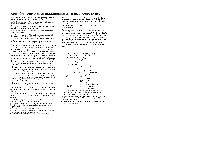
ANTENNA CONNECTION FM Antenna Turn on the POWER switch and tune in an FM station. Then, adjust the length, direction and angle of the telescopic antenna to obtain the best reception. When the reception is unsatisfactory using the telescopic antenna, which could occur in areas far from the FM station, where nearby traffic causes excessive disturbances or where high-rise buildings interfere with the signal transmision, an FM indoor or outdoor antenna (300 ohms) available on the market may be connected to the "FM ANT" terminal instead of using the telescopic antenna. When using an external FM antenna, fold down the telescopic antenna. Note: Please refer to the section on "Band Selector Switches According to Area". Note: Do not carry your system around with the telescopic antenna extended as the antenna might be damaged if struck against something hard. MW (AM) Antenna The built-in ferrite bar antenna may be used to receive local MW (AM) stations. This antenna is a directional type, which means that broadcasts from distant stations may sometimes be improved by rotating the unit, itself. When the ferrite bar antenna is used, the telescopic antenna should be folded down. CONNECTIONS AND POWER SUPPLY * Turntable installation Note the colors, white (L) and red (R), of the record player output jacks, and connect the white jack to the PHONO L (left) terminal and the red jack to the PHONO R (right) terminal on the back panel. * Connection to the recording auxiliary jacks When another tape deck is used in addition to the one housed in the main unit, tape-to-tape dubbing, mixed playback of tape sources, etc. is possible. For this purpose, connect the left and right LINE IN jacks of the tape deck to the left and right auxiliary jacks on the back panel. * Speaker system connection In accordance with the connection diagram, connect the right speaker cord to the right SPEAKER terminals (left and right), and connect the left speaker cord to the left SPEAKER terminals (left and right), making sure the polarities are correctly connected. If the polarities of the speaker cords are reversed, no stereo sound is obtained. Connect the speaker cords to the SPEAKER terminals as follows: While pressing down on the terminal tab just below the terminal, insert one end of the cord into the SPEAKER terminal hole, and then release the tab. This locks the end of the cord in the terminal hole. POWER SUPPLY AC OUTLET * Connect the attached power cord to the AC input jack on the back of the unit. Even though the power cord is connected to. an AC wall outlet, no power is supplied to the unit itself unless the power is turned on. CHECKING THE DC POWER SOURCE (BUILT-IN BATTERIES OR CAR BATTERY) 1. Depress the POWER switch. 2. Note that the indicator above the POWER switch will light up. If the indicator starts to flicker, the batteries are getting weak. If the unit is operated with a weak DC source: * Recording and playback is impossible although radio broadcasts may be heard. In addition, the YMS (Yamaha Music Search) system may fail to work properly. When this condition arises, replace all batteries or operate the unit on AC power. Note on Receiving Bands and Antennas U.S.A. and Canadian models: The telescopic antenna provides reception for the FM band, and the built-in ferrite bar antenna provides reception for the MW (AM) bands. Europe and U.K. models: The telescopic antenna provides reception for the FM and SW bands, and the builtin ferrite bar antenna provides reception for the MW and LW bands. Other Area Models: The telescopic antenna provides reception for the FM and SW, bands and the built-in ferrite bar antenna provides reception for the MW and SW, bands. Band Selector Switches According to Area U.S.A. and Canada Europe and U.K. Other Area FM MW (AM) 87.6 - 525 108.0MHz 1605kHz FM MW LW 87.6 - 525 - 153 - 108.0MHz 1605kHz . 280kHz SW 5.8 16.0MHz FM MW SW, 87.6- 525- 3.0108.0MHz 1605kHz 8.0MHz SW, 8.0 22.0MHz 9
-
 1
1 -
2
-
3
-
 4
4 -
 5
5 -
 6
6 -
 7
7 -
 8
8 -
 9
9 -
 10
10 -
 11
11 -
 12
12 -
 13
13 -
 14
14 -
15
-
16
-
17
 |
 |
