Yamaha QL5 Reference Manual - Page 53
Ch1-64 Post Eq Ql5, St In1l-8r Post Eq, Mix1-16 Post Eq, St L/r, Mono Post Eq
 |
View all Yamaha QL5 manuals
Add to My Manuals
Save this manual to your list of manuals |
Page 53 highlights
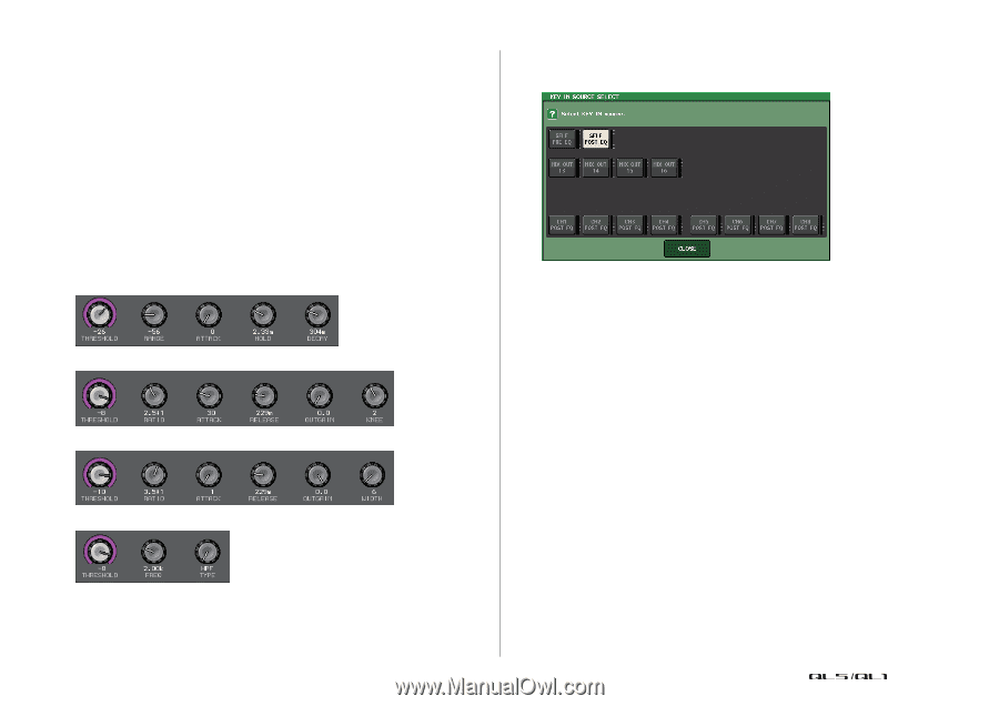
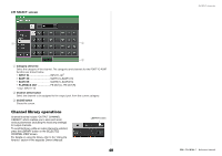
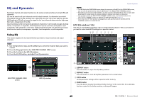
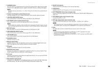
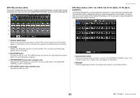
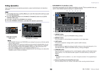
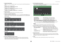
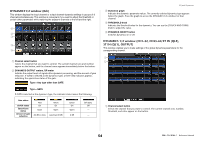
7 Dynamics type buttons Enables you to select the dynamics type. You can choose from the following dynamics types. • Dynamics 1 for an input channel GATE, DUCKING, COMPRESSOR, EXPANDER • Dynamics 2 for an input channel COMPRESSOR, COMPANDER-H, COMPANDER-S, DE-ESSER • Dynamics 1 for an output channel COMPRESSOR, EXPANDER, COMPANDER-H, COMPANDER-S 8 Dynamics graph Displays the input/output response of the dynamics processors. 9 Dynamics parameter setting knobs Indicates the dynamics parameter values. You can use the [TOUCH AND TURN] knob to adjust the values. The type of parameters will vary depending on the currently-selected dynamics type. • GATE or DUCKING: • COMPRESSOR or EXPANDER: • COMPANDER-H or COMPANDER-S: • DE-ESSER: 0 Dynamics IN/OUT level meters, GR meter These meters indicate the peak level of the signals before and after the dynamics processing, and the amount of gain reduction. For a stereo channel, these meters indicate the level of both the L and R channels. EQ and Dynamics A KEY IN SOURCE select button Press this button to display the KEY IN SOURCE SELECT window, in which you can select a key-in signal that will trigger the dynamics. • SELF PRE EQ The pre-EQ signal of the same channel. • SELF POST EQ The post-EQ signal of the same channel. • MIX OUT 13-16 Output signals of MIX channels 13-16 • CH1-64 POST EQ (QL5), CH1-32 POST EQ (QL1), ST IN1L-8R POST EQ, MIX1-16 POST EQ, MTRX1-8 POST EQ, ST L/R, MONO POST EQ The post-EQ signal of the corresponding channel*1 *1. The selectable signals are limited to the corresponding eight-channel group. NOTE In the case of QL1, channels that do not exist on the model will not be shown. B KEY IN FILTER parameter area (Displayed only for Gate or Ducking) Enables you to make various settings for a filter that lets the key-in signal pass. • Filter select buttons Select the type of filter from HPF, BPF, or LPF. To disable the filter, press the button that is turned on. • Q knob Indicates the filter Q. You can use the [TOUCH AND TURN] knob to adjust the value. • FREQUENCY knob Indicates the filter cutoff frequency. You can use the [TOUCH AND TURN] knob to adjust the value. C KEY IN CUE button Enables you to cue-monitor the signal that has been selected as the KEY IN SOURCE signal. Cue will be canceled if you have selected a dynamics type that does not feature this button, or if you move to a different screen. D Tabs Use these tabs to select a channel that you want to view on the screen. 53 Reference Manual
-
 1
1 -
2
-
3
-
4
-
5
-
6
-
7
-
8
-
9
-
10
-
11
-
12
-
13
-
14
-
15
-
16
-
17
-
18
-
19
-
20
-
21
-
22
-
23
-
24
-
25
-
26
-
27
-
28
-
29
-
30
-
31
-
32
-
33
-
34
-
35
-
36
-
37
-
38
-
39
-
40
-
41
-
42
-
43
-
44
-
45
-
46
-
47
-
 48
48 -
 49
49 -
 50
50 -
 51
51 -
 52
52 -
 53
53 -
 54
54 -
 55
55 -
 56
56 -
 57
57 -
 58
58 -
59
-
60
-
61
-
62
-
63
-
64
-
65
-
66
-
67
-
68
-
69
-
70
-
71
-
72
-
73
-
74
-
75
-
76
-
77
-
78
-
79
-
80
-
81
-
82
-
83
-
84
-
85
-
86
-
87
-
88
-
89
-
90
-
91
-
92
-
93
-
94
-
95
-
96
-
97
-
98
-
99
-
100
-
101
-
102
-
103
-
104
-
105
-
106
-
107
-
108
-
109
-
110
-
111
-
112
-
113
-
114
-
115
-
116
-
117
-
118
-
119
-
120
-
121
-
122
-
123
-
124
-
125
-
126
-
127
-
128
-
129
-
130
-
131
-
132
-
133
-
134
-
135
-
136
-
137
-
138
-
139
-
140
-
141
-
142
-
143
-
144
-
145
-
146
-
147
-
148
-
149
-
150
-
151
-
152
-
153
-
154
-
155
-
156
-
157
-
158
-
159
-
160
-
161
-
162
-
163
-
164
-
165
-
166
-
167
-
168
-
169
-
170
-
171
-
172
-
173
-
174
-
175
-
176
-
177
-
178
-
179
-
180
-
181
-
182
-
183
-
184
-
185
-
186
-
187
-
188
-
189
-
190
-
191
-
192
-
193
-
194
-
195
-
196
-
197
-
198
-
199
-
200
-
201
-
202
-
203
-
204
-
205
-
206
-
207
-
208
-
209
-
210
-
211
-
212
-
213
-
214
-
215
-
216
-
217
-
218
-
219
-
220
-
221
-
222
-
223
-
224
-
225
-
226
-
227
-
228
-
229
-
230
-
231
-
232
-
233
-
234
-
235
-
236
-
237
-
238
-
239
-
240
-
241
-
242
-
243
-
244
-
245
-
246
-
247
-
248
-
249
-
250
-
251
-
252
-
253
-
254
-
255
-
256
-
257
-
258
-
259
-
260
-
261
-
262
-
263
-
264
 |
 |