Yamaha YSP 3000 Owner's Manual - Page 25
Connections using HDMI cables
 |
UPC - 027108928616
View all Yamaha YSP 3000 manuals
Add to My Manuals
Save this manual to your list of manuals |
Page 25 highlights
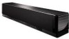
PREPARATION Connections Connections using HDMI cables This unit is equipped with 2 HDMI input jacks and 1 HDMI output jack. If your TV and other components have HDMI jacks, use HDMI cables for simpler and easier connections, and you can skip the connection procedures from page 22 to 25. If your TV has a built-in digital satellite tuner and an optical digital output jack, connect the optical digital output jack on your TV to the TV/STB OPTICAL DIGITAL INPUT jack on this unit. Notes • Even if you connect your TV and this unit via the HDMI jack, you need to connect the video input jack on your TV to the VIDEO OUT jack on this unit in order to display the OSD of this unit. • When HDMI CONTROL is set to OFF (see page 82) and this unit is in the standby mode, the signals input at the HDMI IN jacks are not output at the HDMI OUT jack. y We recommend that you secure the HDMI cable(s) with adhesive tape, etc. once you have connected the HDMI cable(s) to the HDMI jack(s) of this unit. Rear panel of this unit OUT VIDEO SUBWOOFER DIGITAL INPUT AUX 2 DVD COAXIAL OPTICAL AUX 1 TV/STB AUX 1 DVD IN OUT HDMI * This connection (except for a game console) is not necessary if your TV has a built-in digital satellite tuner, cable TV tuner, or digital airwave tuner. A A A Video input Optical digital output HDMI input HDMI output HDMI output TV Audio/Video A HDMI cable DVD player/recorder Digital satellite tuner, cable TV tuner, digital airwave tuner, or game console Video OSD video pin cable Audio Optical cable 21 En English
-
 1
1 -
2
-
3
-
4
-
5
-
6
-
7
-
8
-
9
-
10
-
11
-
12
-
13
-
14
-
15
-
16
-
17
-
18
-
19
-
 20
20 -
 21
21 -
 22
22 -
 23
23 -
 24
24 -
 25
25 -
 26
26 -
 27
27 -
 28
28 -
 29
29 -
 30
30 -
31
-
32
-
33
-
34
-
35
-
36
-
37
-
38
-
39
-
40
-
41
-
42
-
43
-
44
-
45
-
46
-
47
-
48
-
49
-
50
-
51
-
52
-
53
-
54
-
55
-
56
-
57
-
58
-
59
-
60
-
61
-
62
-
63
-
64
-
65
-
66
-
67
-
68
-
69
-
70
-
71
-
72
-
73
-
74
-
75
-
76
-
77
-
78
-
79
-
80
-
81
-
82
-
83
-
84
-
85
-
86
-
87
-
88
-
89
-
90
-
91
-
92
-
93
-
94
-
95
-
96
-
97
-
98
-
99
-
100
-
101
-
102
-
103
-
104
-
105
-
106
-
107
-
108
-
109
-
110
-
111
-
112
-
113
-
114
-
115
-
116
-
117
-
118
-
119
-
120
-
121
-
122
-
123
-
124
-
125
-
126
-
127
-
128
-
129
 |
 |
