2005 Volvo S40 Owner's Manual - Page 116
2005 Volvo S40 Manual
Page 116 highlights
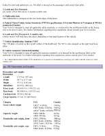
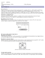
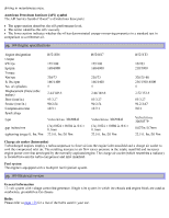
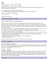
driving in mountainous areas. American Petroleum Institute (API) symbol The API Service Symbol "donut" is divided into three parts: The upper section describes the oil's performance level. The center identifies the oil's viscosity. The lower section indicates whether the oil has demonstrated energy-conserving properties in a standard test in comparison to a reference oil. pg. 188 Engine specifications Engine designation Output kW/rps hp/rpm Torque Nm/rps ft. lbs./rpm No. of cylinders Displacement (liters/cubic inches) Bore (mm/in.) Stroke (mm/in.) Compression ratio Spark plugs type gap inches/mm tightening torque ft. lbs./Nm B5244S4 125/100 168/6000 230/73 166/4400 5 2.44/148.6 83/3.27 90/3.54 10.3:1 Volvo kit no. 30650843 (3x) 0.024 ± 0.004 in./0.6 ± 0.1mm 22.5 ft. lbs./30 Nm B5244S7 125/100 168/6000 230/73 166/4400 5 2.44/148.6 83/3.27 90/3.54 10.3:1 Volvo kit no. 30650843 (3x) 0.024 ± 0.004 in./0.6 ± 0.1mm 22.5 ft. lbs./30 Nm B5254T3 162/83 218/5000 320/25-80 236/1500-4800 5 2.52/153.8 83/3.27 93.2/3.67 9.0:1 Volvo kit no. 30650379 0.027in./0.7mm 22.5 ft. lbs./30 Nm Charge air cooler (Intercooler) Turbocharged engines employ a turbocompressor to force air into the engine inlet manifold and a charge air cooler to cool the compressed inlet air. The resulting increase in air flow raises pressure in the intake manifold and increases engine power over that developed by the normally-aspirated engine. The charge air cooler (which resembles a radiator) is located between the turbo-compressor and inlet manifold. Fuel system The engine is equipped with a multiport fuel injection system. pg. 189 Electrical system General information 12-volt system with voltage controlled generator. Single wire system in which the chassis and engine block are used as conductors, grounded on the chassis. Bulbs Please refer to page 155 for a list of the bulbs used in your car.
-
 1
1 -
2
-
3
-
4
-
5
-
6
-
7
-
8
-
9
-
10
-
11
-
12
-
13
-
14
-
15
-
16
-
17
-
18
-
19
-
20
-
21
-
22
-
23
-
24
-
25
-
26
-
27
-
28
-
29
-
30
-
31
-
32
-
33
-
34
-
35
-
36
-
37
-
38
-
39
-
40
-
41
-
42
-
43
-
44
-
45
-
46
-
47
-
48
-
49
-
50
-
51
-
52
-
53
-
54
-
55
-
56
-
57
-
58
-
59
-
60
-
61
-
62
-
63
-
64
-
65
-
66
-
67
-
68
-
69
-
70
-
71
-
72
-
73
-
74
-
75
-
76
-
77
-
78
-
79
-
80
-
81
-
82
-
83
-
84
-
85
-
86
-
87
-
88
-
89
-
90
-
91
-
92
-
93
-
94
-
95
-
96
-
97
-
98
-
99
-
100
-
101
-
102
-
103
-
104
-
105
-
106
-
107
-
108
-
109
-
110
-
 111
111 -
 112
112 -
 113
113 -
 114
114 -
 115
115 -
 116
116 -
 117
117 -
 118
118 -
 119
119 -
 120
120 -
 121
121 -
122
-
123
-
124
-
125
-
126
-
127
 |
 |