3Com 2226 User Guide - Page 12
(6) Duplex LEDs, (7) Self-Adhesive Pads, Rear Panel, (8) Power Supply, (9) Recovery Button - plus
 |
UPC - 662705479828
View all 3Com 2226 manuals
Add to My Manuals
Save this manual to your list of manuals |
Page 12 highlights
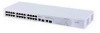
12 CHAPTER 1: INTRODUCING THE BASELINE SWITCH (6) Duplex LEDs The second and fourth (bottom) row of Status LEDs, which are colored yellow, show the duplex status of the related ports. Status Off Yellow Meaning No link, link is not yet negotiated, or the port is operating in half-duplex mode The port is operating in full-duplex mode (7) Self-Adhesive Pads The unit is supplied with four self-adhesive rubber pads. Do not apply the pads if you intend to rack-mount the unit. If the unit is to be part of a free-standing stack, apply the pads to each marked corner area on the underside of the unit. Place the unit on top of the lower unit, ensuring that the pads locate with the recesses of the lower unit. Rear Panel (8) Power Supply The Switch automatically adjusts to the supply voltage. Only use the power cord that is supplied with the unit. (9) Recovery Button Use the Recovery button on the rear panel to reset the Switch to its factory defaults. For more informa- tion, refer to "Resetting to Factory Defaults" on page 43. Package Contents The 3Com Baseline Switch 2226 Plus package includes the following items: ■ One 3Com Baseline Switch 2226 Plus unit ■ One power cord ■ Four standard height, self-adhesive rubber pads ■ One mounting kit ■ One CD-ROM, which contains this User Guide and the 3Com Discovery application ■ One warranty flyer Before installing and using the Switch, verify that your Switch package has all these items. If any of the above items are damaged or missing, contact your 3Com network supplier immediately.
-
 1
1 -
2
-
3
-
4
-
5
-
6
-
 7
7 -
 8
8 -
 9
9 -
 10
10 -
 11
11 -
 12
12 -
 13
13 -
 14
14 -
 15
15 -
 16
16 -
 17
17 -
18
-
19
-
20
-
21
-
22
-
23
-
24
-
25
-
26
-
27
-
28
-
29
-
30
-
31
-
32
-
33
-
34
-
35
-
36
-
37
-
38
-
39
-
40
-
41
-
42
-
43
-
44
-
45
-
46
-
47
-
48
-
49
-
50
-
51
-
52
-
53
-
54
-
55
-
56
-
57
-
58
-
59
-
60
-
61
-
62
-
63
-
64
-
65
-
66
-
67
-
68
-
69
 |
 |
