3Com 3C17203 Getting Started Guide - Page 26
The Power-up Sequence, Powering-up the Switch 4400, Checking for Correct Operation of LEDs
 |
UPC - 662705363738
View all 3Com 3C17203 manuals
Add to My Manuals
Save this manual to your list of manuals |
Page 26 highlights
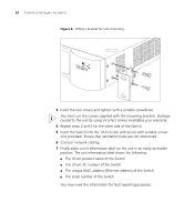
26 CHAPTER 2: INSTALLING THE SWITCH 3Com recommends that you initialize a Switch 4400 unit that has previously been used elsewhere in your network before you add it to an existing stack. If you do not initialize the unit, problems may be caused by conflicting Switch configurations. When the Switch 4400s are stacked together they are assigned a unit number from bottom-to-top for management purposes. When further switches are added to the stack, they can be positioned at the bottom of the stack or at the top. Either way, the Switch management software will re-order the Switch unit numbers into a logical order again (from bottom to top). The Power-up Sequence The following sections describe how to get your Switch 4400 powered-up and ready for operation. Powering-up the Use the following sequence of steps to power-up the Switch. Switch 4400 1 Plug the power cord into the power socket at the rear of the Switch. 2 Plug the other end of the power cord into your power outlet. The Switch powers-up and runs through its Power On Self Test (POST), which takes approximately 10 seconds. Checking for Correct Operation of LEDs During the Power On Self Test, all ports on the Switch are disabled and the LEDs light in a set sequence. When the POST has completed, check the Power/Self Test LED to make sure that your Switch is operating correctly. Table 7 shows possible colors for the LED. Table 7 Power/Self Test LED colors Color Green Yellow Off State The Switch is powered-up and operating normally. The Switch has failed its Power On Self Test. This occurs if any of the ports fail during power-up. The Switch is not receiving power. If there is evidence of a problem, see "Solving Problems Indicated by LEDs" on page 48.
-
 1
1 -
2
-
3
-
4
-
5
-
6
-
7
-
8
-
9
-
10
-
11
-
12
-
13
-
14
-
15
-
16
-
17
-
18
-
19
-
20
-
 21
21 -
 22
22 -
 23
23 -
 24
24 -
 25
25 -
 26
26 -
 27
27 -
 28
28 -
 29
29 -
 30
30 -
 31
31 -
32
-
33
-
34
-
35
-
36
-
37
-
38
-
39
-
40
-
41
-
42
-
43
-
44
-
45
-
46
-
47
-
48
-
49
-
50
-
51
-
52
-
53
-
54
-
55
-
56
-
57
-
58
-
59
-
60
-
61
-
62
-
63
-
64
-
65
-
66
-
67
-
68
-
69
-
70
-
71
-
72
-
73
-
74
-
75
-
76
 |
 |