3Com 3C17400 User Manual - Page 37
Connecting the Workstation to the Switch, Appendix B,
 |
View all 3Com 3C17400 manuals
Add to My Manuals
Save this manual to your list of manuals |
Page 37 highlights
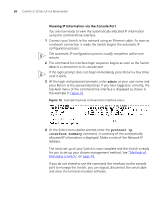
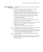
Viewing Automatically Configured IP Information 37 You can find pin-out diagrams for the cable in Appendix B on page 57. ■ A Category 5 twisted pair Ethernet cable with RJ-45 connectors to connect your Switch to the network. Connecting the Workstation to the Switch 1 Connect the workstation to the console port using a standard null modem cable as shown in Figure 9. Figure 9 Connecting a workstation to the Switch via the console port Workstation (with terminal emulation software installed) Switch Standard Null Modem Cable Console Port Connection To connect the cable: a Attach the female connector on the cable to the male connector on the console port of the Switch. b Tighten the retaining screws on the cable to prevent it from being loosened. c Connect the other end of the cable to one of the serial ports (also known as a COM port) on your workstation. 2 Open your terminal emulation software and configure the COM port settings to which you have connected the cable. The settings should be set to match the default settings for the Switch, which are: ■ 19,200 baud ■ 8 data bits ■ no parity ■ 1 stop bit ■ no hardware flow control Refer to the documentation that accompanies the terminal emulation software for more information.
-
 1
1 -
2
-
3
-
4
-
5
-
6
-
7
-
8
-
9
-
10
-
11
-
12
-
13
-
14
-
15
-
16
-
17
-
18
-
19
-
20
-
21
-
22
-
23
-
24
-
25
-
26
-
27
-
28
-
29
-
30
-
31
-
 32
32 -
 33
33 -
 34
34 -
 35
35 -
 36
36 -
 37
37 -
 38
38 -
 39
39 -
 40
40 -
 41
41 -
 42
42 -
43
-
44
-
45
-
46
-
47
-
48
-
49
-
50
-
51
-
52
-
53
-
54
-
55
-
56
-
57
-
58
-
59
-
60
-
61
-
62
-
63
-
64
-
65
-
66
-
67
-
68
-
69
-
70
-
71
-
72
 |
 |
