AIWA CDC-X227 Service Manual
AIWA CDC-X227 Manual
 |
View all AIWA CDC-X227 manuals
Add to My Manuals
Save this manual to your list of manuals |
AIWA CDC-X227 manual content summary:
- AIWA CDC-X227 | Service Manual - Page 1
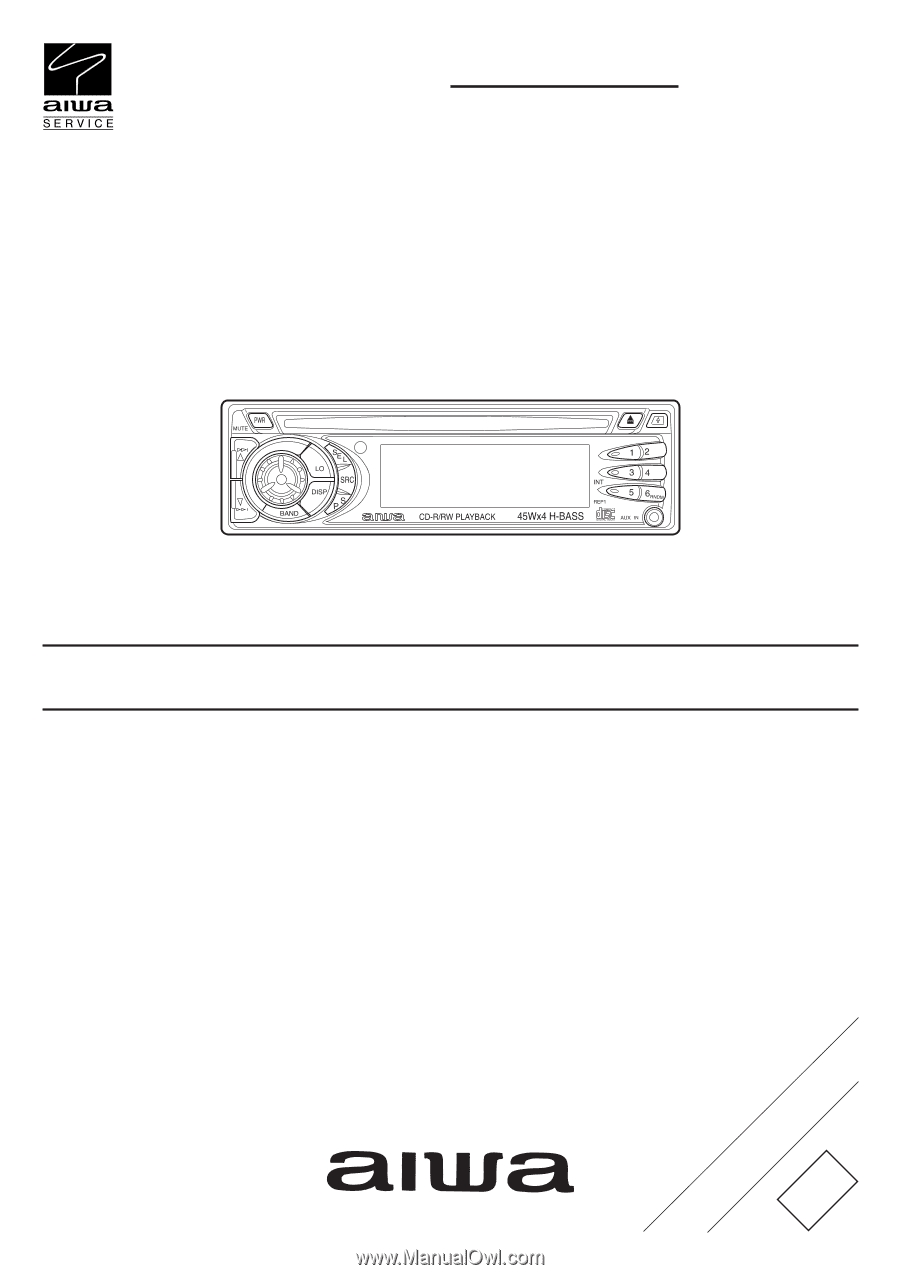
CDC-X227 YZ SERVICE MANUAL STEREO CAR CD RECEIVER BASIC CD MECHANISM : BZG-3 BNF • This Service Manual is the "Revision Publishing" and replaces "Simple Manual" CDC-X227, (S/M Code No. 09-022-454-4T2). S/M Code No. 09-025-454-4R2 REVISION DATA - AIWA CDC-X227 | Service Manual - Page 2
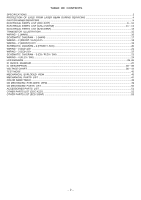
CAUTION WHEN SERVICING ...5 ELECTRICAL PARTS LIST (CDC-X227) ...6 ~ 10 ELECTRICAL PARTS LIST (CZA-4 SNYNF) ...11 ~ 13 ELECTRICAL PARTS LIST (BZG-3 BNF) ...14 TRANSISTOR ILLUSTRATION ...15 WIRING - 1 (MAIN) ...16 SCHEMATIC DIAGRAM - 1 (MAIN) ...17 WIRING - 2 (FRONT / AUX) ...18 WIRING - 2 (FRONT - AIWA CDC-X227 | Service Manual - Page 3
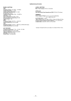
S/N Ratio: 70 dB Stereo Separation: 35 dB at Usable Sensitivity: 30 µV (30 dB) CD SECTION Frequency Response: 17 Hz - 20 channels AUX input Input Sensitivity (load impedance) AUX: Installed Size: 182 (W) x 53 (H) x 155 (D) mm • Design and specifications are subject to change without notice. - 3 - - AIWA CDC-X227 | Service Manual - Page 4
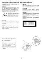
SERVICING This set employs laser. Therefore, be sure to follow carefully the instructions below when servicing. WARNING!! WHEN SERVICING une dangereuse exposition aux radiations. ADVARSEL ling. This Compact Disc player is classified as a connection, remove solder shown in right figure. Solder - 4 - - AIWA CDC-X227 | Service Manual - Page 5
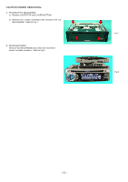
CAUTION WHEN SERVICING 1. Procedure For Disassembly 1) Remove COVER TOP and COVER BOTTOM. 2) Remove the screws (indicated with arrows) from CD MECHANISM. Refer to Fig. 1 2. Servicing Position Remove CD MECHANISM and check the movement while in a stable condition. Refer to Fig-2 Fig-1 Fig-2 - 5 - - AIWA CDC-X227 | Service Manual - Page 6
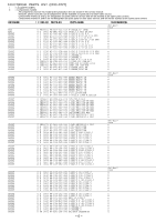
ELECTRICAL PARTS LIST (CDC-X227) ! = ! SAFETY PARTS C = Components marked All components used on this model at the production line are shown in this service manual. However, please note that not all components will be available as spare parts for after-sales service. Components marked S and O are - AIWA CDC-X227 | Service Manual - Page 7
service manual. However, please note that not all components will be available as spare parts for after-sales service. Components marked S and O are designated as spare parts for service and will be stocked at the spare parts 87-010-786-080 C-CAP,U 0.018-25 K B GRM CDC-X227 YZSF a a a a a a a a a a - AIWA CDC-X227 | Service Manual - Page 8
service manual. However, please note that not all components will be available as spare parts for after-sales service. Components marked S and O are designated as spare parts for service and will be stocked at the spare parts 87-010-759-080 C-CAP,U 0.1-25 Z F CM/CB CDC-X227 YZSF a a a a a a a a a a - AIWA CDC-X227 | Service Manual - Page 9
service manual. However, please note that not all components will be available as spare parts for after-sales service. Components marked S and O are designated as spare parts for service and will be stocked at the spare parts R 0416 88-108-102-080 C-RES,U 1K-1/16W J CDC-X227 YZSF a a a a a a a a a a - AIWA CDC-X227 | Service Manual - Page 10
MAIN O SW 0901 87-A91-070-010 SW,TACT SKHHLV O TU 0101 8C-KCG-622-010 TU UNIT, FAE347-A31 X W 0801 8A-KCG-615-010 WIRE,400 P-MUTE O X 0901 87-A70-362-080 VIB,XTAL 4.5MHZ HC-49/U-S CDC-X227 YZSF a a a a - 10 - - AIWA CDC-X227 | Service Manual - Page 11
and will be stocked at the spare parts centers. Components marked X and R are not designated as spare parts for after sales service, and will not be stocked at the spare parts centers. UNIT-NAME CD CD CD CD CD CD CD CD CD CD ! C REF-NO PARTS-NO PARTS-NAME O C 0201 87-010-553-040 CAP,E 47-16 - AIWA CDC-X227 | Service Manual - Page 12
and will be stocked at the spare parts centers. Components marked X and R are not designated as spare parts for after sales service, and will not be stocked at the spare parts centers. UNIT-NAME CD CD CD CD CD CD CD CD CD CD ! C REF-NO PARTS-NO PARTS-NAME X R 0208 88-108-153-080 C-RES,U 15K - AIWA CDC-X227 | Service Manual - Page 13
O are designated as spare parts for service and will be stocked at the spare parts centers. Components marked X and R are not designated as spare parts for after sales service, and will not be stocked at the spare parts centers. UNIT-NAME CD CD ! C REF-NO PARTS-NO PARTS-NAME SUFFIX&MODEL CZA - AIWA CDC-X227 | Service Manual - Page 14
production line are shown in this service manual. However, please note that not all components will be available as spare parts for after-sales service. Components marked S and O are designated as spare parts for service and will be stocked at the spare parts centers. Components marked X and R are - AIWA CDC-X227 | Service Manual - Page 15
CHIP RESISTOR PART CODE Chip Resistor Part Coding 88 A Resistor Code Chip resistor Wattage 1/16W 1/16W 1/10W 1/8W Type 1005 1608 2125 3216 Tolerance 5% 5% 5% 5% Figure Value of resistor Symbol CJ CJ CJ CJ Dimensions (mm) Form LW : A t Resistor Code : A 1.0 0.5 0.35 104 L t 1.6 0.8 0.45 - AIWA CDC-X227 | Service Manual - Page 16
WIRING - 1 (MAIN) 32 31 30 29 28 27 26 25 24 23 22 21 20 19 18 17 16 15 14 13 12 11 10 9 8 7 6 5 4 3 2 1 A B C D E F G H I J K L M N O P Q R S T U - 16 - - AIWA CDC-X227 | Service Manual - Page 17
SCHEMATIC DIAGRAM - 1 (MAIN) - 17 - - AIWA CDC-X227 | Service Manual - Page 18
WIRING - 2 (FRONT / AUX) 32 31 30 29 28 27 26 25 24 23 22 21 20 19 18 17 16 15 14 13 12 11 10 9 8 7 6 5 4 3 2 1 A B C D E F G H I J K L M N O P Q R S T U - 18 - - AIWA CDC-X227 | Service Manual - Page 19
WIRING - 2 (FRONT) 1 2 3 4 5 6 7 8 9 10 11 12 13 14 15 16 17 18 19 20 21 22 23 24 25 26 27 28 29 30 31 32 A B C D E F G H I J K L M N O P Q R S T U - 19 - - AIWA CDC-X227 | Service Manual - Page 20
SCHEMATIC DIAGRAM - 2 (FRONT / AUX) - 20 - - AIWA CDC-X227 | Service Manual - Page 21
WIRING - 3 (CD) 32 31 30 29 28 27 26 25 24 23 22 21 20 19 18 17 16 15 14 13 12 11 10 9 8 7 6 5 4 3 2 1 A B C D E F G H I J K L M N O P Q R S T U - 21 - - AIWA CDC-X227 | Service Manual - Page 22
WIRING - 3 (CD) 1 2 3 4 5 6 7 8 9 10 11 12 13 14 15 16 17 18 19 20 21 22 23 24 25 26 27 28 29 30 31 32 A B C D E F G H I J K L M N O P Q R S T U - 22 - - AIWA CDC-X227 | Service Manual - Page 23
SCHEMATIC DIAGRAM _ 3 (CD / FLEX / SW) - 23 - - AIWA CDC-X227 | Service Manual - Page 24
WIRING - 4 (FLEX / SW) 15 14 13 12 11 10 9 8 7 6 5 4 3 2 1 A B C D E F G H I J K L M N TO CD C.B O P TO CD C.B Q R S T U - 24 - - AIWA CDC-X227 | Service Manual - Page 25
LCD DIAGRAM - 25 - - AIWA CDC-X227 | Service Manual - Page 26
- 26 - - AIWA CDC-X227 | Service Manual - Page 27
IC BLOCK DIAGRAM - 27 - - AIWA CDC-X227 | Service Manual - Page 28
clock for command output or output terminal for sub-code transfer-in clock from 13 CQCK O SQ OUT. Stereo mode. (Not used) 19 NC - Not connected. 20 E-VOL CE O CE output for volume level control. 21 ACC-CONT O Output CD changer ACC signal. (Not used) 22 KS4 O Initial setting - AIWA CDC-X227 | Service Manual - Page 29
OPEN I SW2 I SW1 I R-ENCOD2 I R-ENCOD1 I LCD-DI I REMOTE IN I LED O CD DISP SEL O CD CLOCK OUT O CD DATA OUT O CD CONNECT I CD INSIDE I TEST I L IND I PH. MUTE I RESET I ACC IN I SNS I BATT IN I IF (FM/AM) I E03 - SUB PD - VDD - AM OSC I FM OSC I VSS - AIWA CDC-X227 | Service Manual - Page 30
the TE signal. For the connection of a resistor which sets the gain of the TE signal between this pin and the O TE pin. O TE signal output. I TES (track error sense) comparator input. The signal is passed through a BPF. I Shock detection input. I Sets the time constant for the tracking gain - AIWA CDC-X227 | Service Manual - Page 31
switches the focus search modes (+/-search / +search with I respect to the reference voltage). (Connected to D-GND) - VCC of servo and digital circuits. - For the connection of bypass capacitor for the reference voltage. O Reference voltage output. - Set the time constant for disc defect - AIWA CDC-X227 | Service Manual - Page 32
in. (Must be connected to 0V.) O Disc motor control output. Can be set to three-value output microprocessor O command. O EFM data playback clock monitor. Output 4.3218 MHz when the phase possible for all commands. (Must be connected to 0V.) O Left channel mute output. (Not used) - Left channel - AIWA CDC-X227 | Service Manual - Page 33
2M TEST5 CS TEST1 I/O Description O Right channel mute output. (Not used) - Crystal oscillator power supply. O Connection for a 16.93 MHz crystal oscillator element. I - Crystal oscillator ground. (Must be connected to 0V.) O Subcode clock synchronization signal output. (Not used) O C1 - AIWA CDC-X227 | Service Manual - Page 34
AUX(L) 36 CHG(L) 37 TUN(L) 38 CD(L) 39 VDD 40 CD(R) I/O Description I 4dB volume control input. Must be driven at a low impedance. - 1dB volume control common pin. For the connection A capacitor must be connected between VREF and VSS as a troubleshooting against power ripples. O - AIWA CDC-X227 | Service Manual - Page 35
Pin No. 41 42 43 44 Pin Name TUN(R) CHG(R) AUX(R) RSELO I/O I Signal input pins. - Not used. I Signal pins have build-in pull-down resistor. 53 ~ 54 KI4 ~ KI5 - Connected to GND. 55 TEST - Test pin. (Connected to GND.) 56 VDD - Power supply. Used for applying the LCD drive - AIWA CDC-X227 | Service Manual - Page 36
0 0 0 0 PIN NO. 42 43 44 45 46 47 48 49 50 51 52 53 54 55 56 57 58 59 60 61 62 63 64 CD 2.4 2.41 2.5 0 2.51 2.41 0 0 2.41 4.8 DATA DATA 4.84 0 4.93 2.51 2.51 2.39 2.5 2.22 3.71 0.19 4.91 TUNER 0 0 0 0 0 0 0 0 0 0 0 0 0 0 0 0 0 0 0 0 0 0 0 AUX 0 0 0 0 0 0 0 0 0 0 0 0 0 0 0 0 0 0 0 0 0 0 0 - 36 - - AIWA CDC-X227 | Service Manual - Page 37
38 0 39 0 40 2.03 41 4.96 TUNER 0 0 0 0 0 0 0 0 0 0 0 0 0 0 0 0 0 0 0 0 0 0 0 0 0 0 0 0 0 0 0 0 0 0 0 0 0 0 0 0 0 AUX 0 0 0 0 0 0 0 0 0 0 0 0 0 0 0 0 0 0 0 0 0 0 0 0 0 0 0 0 0 0 0 0 0 0 0 0 0 0 0 0 0 PIN NO. CD TUNER AUX 42 0 0 0 43 4.79 0 0 44 1.75 0 0 45 1.85 0 0 46 - AIWA CDC-X227 | Service Manual - Page 38
2.58 25 4.7 26 0 27 0 28 0 29 0 30 0 TUNER 0 0 0 0 0 0 0 0 0 0 0 0 0 0 0 0 0 0 0 0 0 0 0 0 0 0 0 0 0 0 AUX 0 0 0 0 0 0 0 0 0 0 0 0 0 0 0 0 0 0 0 0 0 0 0 0 0 0 0 0 0 0 IC401, LC75374E PIN NO. CD 1 4.2 2 4.26 3 4.26 4 4.28 5 4.28 6 4.28 7 4.28 8 0 TUNER 4.2 4.26 4.26 - AIWA CDC-X227 | Service Manual - Page 39
45 11 2.45 12 2.45 13 2.45 TUNER 4.7/0 0/4.7 4.7/0 4.8 2.45 2.45 2.45 2.45 2.45 2.45 2.45 2.45 2.45 AUX 4.7/0 0/4.7 4.7/0 4.8 2.45 2.45 2.45 2.45 2.45 2.45 2.45 2.45 2.45 PIN NO. CD TUNER AUX 14 2.45 2.45 2.45 15 2.45 2.45 2.45 16 2.45 2.45 2.45 17 2.45 2.45 2.45 18 2.45 - AIWA CDC-X227 | Service Manual - Page 40
4.9 3.26 1.65 0 0.8 4.9 DATA DATA DATA TUNER 0 4.9 3.26 1.65 0 0.8 4.9 DATA DATA DATA AUX 0 4.9 3.26 1.65 0 0.8 4.9 DATA DATA DATA IC901, LC72358N-9A71 PIN NO. CD TUNER 1 2.4 2.4 2 0 0 3 0 0 4 0 0 5 0 0 6 DATA DATA 7 4.95 4.95 8 DATA DATA 9 DATA DATA 10 DATA DATA - AIWA CDC-X227 | Service Manual - Page 41
PIN NO. 70 71 72 73 74 75 76 77 78 79 80 CD TUNER AUX 0 2.51 0 0 0 0 0 0 0 4.88 4.89 4.88 0 0/2.34 0 0 2.45/0 0 0 0 0 0 0 0 0.97 0.97 1.02 0 0 0 2.49 2.46 2.47 TU101, FAE347-A31 PIN NO. ANT INPUT OPEN FM AM 1 0 0 2 0 0 3 0 0 4 7.82 0.2 5 0 0 6 - AIWA CDC-X227 | Service Manual - Page 42
REF. NO. PIN NO. CD FM AM AUX B 1.05 1.06 1.05 1.04 Q101 C 1.4 3.42 3.39 1.7 E 0.59 0.6 0.6 0.59 B 9.16 9.06 8.6 9.2 Q105 C 0 0.36 9.2 0 E 9.38 9.2 9.3 9.45 B 9.24 9.0 0.03 9.24 Q106 C 9.45 9.2 9.3 9.44 E 8.54 8.3 0 8.54 B 0 0 4.78 0 Q107 C - AIWA CDC-X227 | Service Manual - Page 43
B C E B C E B C E B C E B C E B C E B C E B C E B C E CD 0 0 0 0 0 0 0 0 0 0 0 0 4.85 0.03 0 0 0 0.03 1.1 4.1 0.5 7.89 0 4.6 7.97 0 0 0 0 0 4.8 0.03 0 0 0.8 0.03 1.1 4.1 0.5 7.89 0 4.6 7.97 0 4.86 13.64 14.31 14.39 AUX 0 0 0 0 0 0 0 0 0 0 0 0 4.85 0.03 0 0 0.8 0.03 1.1 4.1 0.5 7.89 0 4.6 7.97 0 - AIWA CDC-X227 | Service Manual - Page 44
Q833 Q941 PIN NO. B C E B C E B C E B C E B C E B C E B C E CD 4.81 0.06 0 6.18 13.2 5.54 10.03 14.17 9.36 7.8 14.3 7.2 7.1 7.8 7.9 4.84 0.05 0 6.8 0 14.38 0 14.23 0 14.38 0 14.23 0 6.8 0 4.63 AUX 4.68 0.06 0 6.18 13.2 5.6 10.1 14.32 9.45 0 14.3 0.5 14.34 0 14.35 0 14.34 0 6.8 0 4.63 - 44 - - AIWA CDC-X227 | Service Manual - Page 45
1. How to start CD Test Mode 1) Remove the resistor (100Kohms) connected at Pin 63 (test) of IC701 (LC72358N) on main circuit board. Then connect a wire between Pin 73 (VDD) and Pin 63 (test). 2) Connect ACC (red) and BACK UP (yellow) wires of the connector assy to the positive terminal of Power - AIWA CDC-X227 | Service Manual - Page 46
MECHANICAL EXPLODED VIEW 9 8 7 6 4 3 2 5 10 11 12 25 24 22 23 21 20 13 19 17 A 48 26 A 39 56 28 41 27 B 38 B 14 1 18 16 15 37 H I 32 31 36 D 29 30 50 33 34 35 46 48 - 46 - G B 42 BC 54 51 55 K 53 B 49 52 44 40 45 49 F E B B 43 J B G 47 B - AIWA CDC-X227 | Service Manual - Page 47
-256-010 COVER, BOTTOM RDS 8B-KC1-621-010 FUSE,15A 32V 8C-KCG-036-010 CABI, TRIM 16 CDC-X227 YZSF a a a a a a a a a a O MC1051 8A-KT1-645-010 CONN ASSY,8P ISO-BLACK-B a X MC1052 8C-KCG-254-010 HLDR,ISO-WIRE a X MC1053 8C-KCG-255-010 TUBE,ISO WIRE D12 a X MC1054 8A-KCG-615-010 WIRE,400 P-MUTE - AIWA CDC-X227 | Service Manual - Page 48
NAME TABLE Basic color symbol Color Basic color symbol Color Basic color symbol Color B Black C Cream D Orange G Green H Gray L Blue LT Transparent Blue N Gold P Pink R Red S Silver ST Titan Silver T Brown V Violet W White WT Transparent White Y LM Metallic - AIWA CDC-X227 | Service Manual - Page 49
CD MECHANISM EXPLODED VIEW A 3 1 51 4 5 50 A 6 2 13 D B 20 16 14 31 30 D A F 48 7 C 27 45 8 12 10 52 15 28 A 18 29 54 19 26 22 21 23 35 32 10 24 11 25 33 32 47 17 52 E 34 53 9 46 49 MAPIWN PBWB I 38 H 42 41 44 40 39 43 37 B 55 - 49 - 36 G - AIWA CDC-X227 | Service Manual - Page 50
CD MECHANISM PARTS LIST ! = ! SAFETY PARTS C = Components marked All components used on this model at the production line are shown in this service manual. However, please note that not all components will be available as spare parts for after-sales service. Components marked S and O are designated - AIWA CDC-X227 | Service Manual - Page 51
service manual. However, please note that not all components will be available as spare parts for after-sales service. Components marked S and O are designated as spare parts for service and will be stocked at the spare parts ,5*6 TH+ TAPPING ST SUFFIX&MODEL CDC-X227 YZSF a a a a a a a a a - AIWA CDC-X227 | Service Manual - Page 52
OTHERS PARTS LIST (CDC-X227) ! = ! SAFETY PARTS C = Components marked All components used on this model at the production line are shown in this service manual. However, please note that not all components will be available as spare parts for after-sales service. Components marked S and O are - AIWA CDC-X227 | Service Manual - Page 53
9620450 0251431 2-11, IKENOHATA 1-CHOME, TAITO-KU, TOKYO 110-8710, JAPAN TEL:03 (3827) 3111
-
 1
1 -
 2
2 -
 3
3 -
 4
4 -
 5
5 -
 6
6 -
 7
7 -
8
-
9
-
10
-
11
-
12
-
13
-
14
-
15
-
16
-
17
-
18
-
19
-
20
-
21
-
22
-
23
-
24
-
25
-
26
-
27
-
28
-
29
-
30
-
31
-
32
-
33
-
34
-
35
-
36
-
37
-
38
-
39
-
40
-
41
-
42
-
43
-
44
-
45
-
46
-
47
-
48
-
49
-
50
-
51
-
52
-
53
 |
 |
SERVICE
MANUAL
DATA
CDC-X227
S/M Code No. 09-025-454-4R2
REVISION
YZ
BASIC CD MECHANISM : BZG-3 BNF
•
This Service Manual is the "Revision Publishing" and replaces "Simple Manual"
CDC-X227<YZ>, (S/M Code No. 09-022-454-4T2).
STEREO CAR CD RECEIVER