AIWA CDC-X227 Service Manual - Page 29
AIWA CDC-X227 Manual
 |
View all AIWA CDC-X227 manuals
Add to My Manuals
Save this manual to your list of manuals |
Page 29 highlights
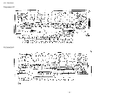
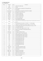
Pin No. 40 41 42 43 44 45 46 47 48 49 50 51 52 53 54 55 56 57 58 59 60 61 62 63 64 65 66 67 68 69 70 71 72 73 74 75 76 77 78 79 80 Pin Name I/O A-MUTE O POWER CONT O ST-BY MUTE O POWER MUTE O BEEP O DFP IN I DRF I WRQ I RWC O CD RES O OPEN I SW2 I SW1 I R-ENCOD2 I R-ENCOD1 I LCD-DI I REMOTE IN I LED O CD DISP SEL O CD CLOCK OUT O CD DATA OUT O CD CONNECT I CD INSIDE I TEST I L IND I PH. MUTE I RESET I ACC IN I SNS I BATT IN I IF (FM/AM) I E03 - SUB PD - VDD - AM OSC I FM OSC I VSS - E02 - E01 O TEST1 - XOUT O Description Audio mute signal output. Power control signal output. ST-BY mute signal output. Power mute signal output. BEEP output (3kHz, 50ms). Front panel detection. "Detect RF" RF level detection input. Pulled up when not used. Sub-code Q output standby input terminal. Read/write control output terminal. DSP reset output terminal. Connected to a pull up resistor. 12 cm disc detection/12 cm disc ejection and detection. Leading motor start detection. Rotary encoder input 2. Rotary encoder input 1. LCD driver data signal input. Remote controller input. Pulled up when not used. Not used. Communication timing signal output to CD changer. "H": TX, "L": RX. (Not used.) Output synchronous clock signal for sending to CD changer. (Not used.) Output data signal for sending to CD changer. (Not used.) Connectivity check to CD changer. (Connected to ground through resistor.) Pick up inner track position detection. CD test mode. Pulled down when not used. Voltage input for level indicator. Pulled down when not used. External mute control. "L"= -20dB mute. Pulled up when not used. System reset. "L"= system reset. ACC (accessory power) ON/OFF input. OFF = Fault mode. Backup detection. Input battery ON/OFF. IF count signal input (FM/AM). Not used. Not used. Power supply. AM channel transmission input. FM channel transmission input. Connected to GND. Not used. Error out from change pump (for FM/AM). Not used. System clock oscillator output. - 29 -
-
 1
1 -
2
-
3
-
4
-
5
-
6
-
7
-
8
-
9
-
10
-
11
-
12
-
13
-
14
-
15
-
16
-
17
-
18
-
19
-
20
-
21
-
22
-
23
-
 24
24 -
 25
25 -
 26
26 -
 27
27 -
 28
28 -
 29
29 -
 30
30 -
 31
31 -
 32
32 -
 33
33 -
 34
34 -
35
-
36
-
37
-
38
-
39
-
40
-
41
-
42
-
43
-
44
-
45
-
46
-
47
-
48
-
49
-
50
-
51
-
52
-
53
 |
 |
