Aastra OpenCom 130 User Guide
Aastra OpenCom 130 Manual
 |
View all Aastra OpenCom 130 manuals
Add to My Manuals
Save this manual to your list of manuals |
Aastra OpenCom 130 manual content summary:
- Aastra OpenCom 130 | User Guide - Page 1
130 OpenCom 100 131 150 Mounting and Commissioning User Guide - Aastra OpenCom 130 | User Guide - Page 2
support or information about other Aastra products, please refer to our website at http://www.aastra.de or http://www.aastra.com. It provides additional notes and tips on the product. OpenCom 100 Product Family This user guide applies to the OpenCom 100 product family comprising the OpenCom 130 - Aastra OpenCom 130 | User Guide - Page 3
Interface Cards 32 Installing an M100-AT4 Card 34 Available Ports 37 OpenCom 130 37 OpenCom 131 38 OpenCom 150 39 Positions of the Ports 41 Interface Cards 43 OpenCom 131 (1 Slot 43 OpenCom 130 (3 Slots 43 OpenCom 150 (5 Slots 46 Port Assignment, Termination, Cable Lengths 48 S0 Ports - Aastra OpenCom 130 | User Guide - Page 4
/Sensor Ports 59 COM Port 60 LAN Port 60 Installing the Memory Card 61 Safety Precautions 61 To Install a Memory Card 62 Aastra 677x: Extensions and Scope of Delivery 75 Configuration 76 Brief Guide to Initial Configuration 77 Configuring the OpenCom 100 79 Preparing the Configuration 79 - Aastra OpenCom 130 | User Guide - Page 5
Updates 86 Resetting the System Data 87 Basic Hardware Settings Switch 87 Generating Your Own MoH Files 88 Configuration Examples 90 OpenCom 100 in Computer Networks 90 Introduction to TCP/IP 91 OpenCom IP (VoIP 102 Quick Start 103 IP System Telephony 103 External SIP Line 104 Internal SIP - Aastra OpenCom 130 | User Guide - Page 6
Services 112 Media Gateway (MGW 113 Software MGW 113 MGW Interface Card 114 SIP Telephony 115 External SIP Connections 115 Internal SIP Subscribers 117 Aastra 673xi/675xi SIP Telephones 120 Aastra 673xi/675xi Setup 122 Aastra 673xi/675xi DHCP 124 Aastra 673xi/675xi Hot Desking 125 VoIP - Aastra OpenCom 130 | User Guide - Page 7
157 Connection via the Public Network 157 Connection via Q.SIG.IP 158 Configuration 159 Bundles 159 Routes 159 Numbering 160 Technical Details Hunt Groups 169 External Call Forwarding 170 Information on the Update 171 PIN Code Telephony 171 Configuration 172 Implementation 173 Switch - Aastra OpenCom 130 | User Guide - Page 8
Users 204 Assigning a Bundle/SIP Trunk 205 Allocating Routing Codes 205 Configuring the Company Exchange 206 Working with the Multi-Company Variant 206 Company Telephone Book 206 Making Calls Between Companies 207 Billing Charges per Company 207 Configuring the PC Software 208 PC Offline - Aastra OpenCom 130 | User Guide - Page 9
Clock 215 18.7 Address Queries using LDAP 216 19. Frequently Asked Questions 217 19.1 General/Hardware 218 19.2 Telephony 219 19.3 PBX Networking 221 19.4 DECT 222 19.5 LAN 223 19.6 Internet 224 20. Technical Specifications 226 21. Notes on Disposal 233 Index 234 7 - Aastra OpenCom 130 | User Guide - Page 10
8 - Aastra OpenCom 130 | User Guide - Page 11
connected to analogue trunk lines. ■ Even with the smallest OpenCom 130 version, it is possible to use all the most important communications applications. The basic module enables telephony with system telephones, IP system telephones, SIP system telephones, standard SIP telephones, ISDN telephones - Aastra OpenCom 130 | User Guide - Page 12
analogue exchange lines. Additional information can be found in the user manual "M100-AT4 Interface Card". ■ The additional S2M connector module allows you to operate an OpenCom 130 / 150 on a primary rate access. Telephony The OpenCom 100 communications system is designed to be connected to an ISDN - Aastra OpenCom 130 | User Guide - Page 13
in accordance with DSS1. A Upn port is suitable for the Aastra 677x (OpenPhone) range of system telephones. RFP 22 / 24 base stations can also be connected to the DECT-enabled Upn ports on interface cards for an OpenCom 130 and an OpenCom 150. An analogue port is used by standard analogue devices - Aastra OpenCom 130 | User Guide - Page 14
or Aastra sales. Cascading Using the expansion module, the OpenCom 130 can be cascaded with a second OpenCom 130 communications system. An Ethernet switch on the expansion module further enables applications featuring media convergence, such as the operation of a VoIP interface card M100-IP. It - Aastra OpenCom 130 | User Guide - Page 15
. If Internet access is already available from an Internet service provider, this can be configured in the OpenCom 100. If the client network is not IP-capable, the OpenCom 100 can administer the IP configuration necessary for Internet access. The OpenCom 100 has an integrated DHCP server and a DNS - Aastra OpenCom 130 | User Guide - Page 16
service provider for incoming mail. When configuring the OpenCom 100, e-mail account query can be configured for every member of staff. The OpenCom OpenCom 100s can connect their LANs by dial-in on demand. A NET CAPI programme (driver software , refer to the user guides called "OpenVoice" and " - Aastra OpenCom 130 | User Guide - Page 17
"Aastra 677x". For users who wish to use PC supported telephony, the IP system terminals are also available as separate licensable software variations (OpenSoftphone). You will find further information in the chapter Voice over IP (VoIP) starting on page 102). DECToverIP® DECT networking via VoIP - Aastra OpenCom 130 | User Guide - Page 18
the slots to be configured before any interface can be commissioned. 2.1 Telephony Functions 2.1.1 OpenCom 130 ■ The S01 port is configured as a multi-terminal connection, and the S02 port as a system port. ■ Aastra 677x system telephones with the telephone numbers 30 to 32 are configured on the - Aastra OpenCom 130 | User Guide - Page 19
100, are not able to make external calls, and have only restricted use of the terminal functions of the OpenCom 100. The "Standard" user group, because of its default settings, is well suited as a starting point for the creation of user groups for normal users of the system (e.g. the staff members - Aastra OpenCom 130 | User Guide - Page 20
are delivered preset for user groups: User group settings Function / Authorisation Applications Configurator Costs Phone Book ISP application Courtesy Service Phone Book Entries (personal) Edit central Dial in (outgoing) External Immediate external line seizure External line seizure over operator - Aastra OpenCom 130 | User Guide - Page 21
Factory Settings on Delivery Authorisations User group settings Function / Authorisation Multiple seizure at the parallel terminal s*) Switch authorization *) Standard Adminis- Guests trators + + + - - - Dial in (incoming) Pickup from group + + - Pickup selective + + - Take Call - Aastra OpenCom 130 | User Guide - Page 22
Factory Settings on Delivery Authorisations User group settings Function / Authorisation MOH at external connections*) MOH at internal connections *) Standard Adminis- Guests trators + + + + + + Protection Call protection ringing ringing off tone tone Call waiting protection + + - - Aastra OpenCom 130 | User Guide - Page 23
Authorisation Programming function keys *) Menu and ABC keys *) DECT trunc keys *) Disconnect ISP connection *) Connection data *) Callback *) E-mail notification *) Send E-mails*) Other *) Speed dialling *) Door opener *) Keypad dialling *) Time control *) SMS stationary *) Booking number may be set - Aastra OpenCom 130 | User Guide - Page 24
. A special list of emergency phone numbers is preset and activated. ■ The door opener can be opened from all terminals. Door calls can be forwarded. ■ Every standard user can change the configuration of OpenCom 100. ■ Every standard user can create a personal telephone book and edit entries in - Aastra OpenCom 130 | User Guide - Page 25
e-mails. ■ Users can disconnect existing Internet connections (via the OpenCom 100 Web console and from a system terminal if the function 192.168.100.10 ■ DHCP addresses: 192.168.99.130 to 192.168.99.169 You can change the IP settings in the Configurator. Check with the network administrator - Aastra OpenCom 130 | User Guide - Page 26
basic module only. Installing the expansion module requires an additional power supply. ■ One set of short user guides ■ One CD including the complete documentation and software The OpenCom 130 expansion set consists of: ■ One expansion module ■ One AC adapter with a connection cable to supply the - Aastra OpenCom 130 | User Guide - Page 27
accessible sockets. Only use the original plug-in power supply: No. 4512699 (TR25240-E-01A13 type) for an OpenCom 131 and for the basic module of an OpenCom 130. The housing cover may only be opened by authorised personnel. Unauthorised opening of the housing cover and improper repair may damage the - Aastra OpenCom 130 | User Guide - Page 28
. 3.3 Declarations of Conformity The OpenCom 130, OpenCom 131 and OpenCom 150 ITC systems conform to the requirements set down in the EU directive 99/5/EC. The Declaration of Conformity can be viewed at the Aastra Web site at http://www.aastra.de or http://www.aastra.com. 3.4 Mounting Location The - Aastra OpenCom 130 | User Guide - Page 29
131 is equipped with a single slot for installing an additional interface card. Installing an expansion set is not necessary. The OpenCom 130 has two separate modules offering more flexibility for extending the system. You can either install the expansion module when you first assemble the system - Aastra OpenCom 130 | User Guide - Page 30
the socket. You should not install the expansion module or install or uninstall additional interface cards while the OpenCom 130 is turned on. 2. Open the housing cover of the OpenCom 130. In this case, carefully follow the Safety Precautions starting on page 25. The existing basic module is mounted - Aastra OpenCom 130 | User Guide - Page 31
LAN0 port of the expansion module. You usually install at least one interface card on the expansion module. To do this, read the instructions in the following section. Please note: Two power supplies are provided for the OpenCom 130 with an expansion module. Always turn on the power supply of 29 - Aastra OpenCom 130 | User Guide - Page 32
power supply. 3.7 Installing Interface Cards The expansion module and the basic module of the OpenCom 130 resp. the main module of the OpenCom 150 can be expanded using interface cards. The main module of the OpenCom 131 is quipped with one large and two small slots for installing interface cards - Aastra OpenCom 130 | User Guide - Page 33
Bell") provides "actor" ports and "sensor" ports. With the OpenCom 130 and the OpenCom 131 systems, an "M100-TFE" interface card can be used. to install one or both of these interface cards: 1. Turn off the OpenCom 100. Open the housing cover. 2. Remove the slot card from the transport packaging. - Aastra OpenCom 130 | User Guide - Page 34
card is connected to the expansion module resp. to the main module via two port jacks. The following properties characterise the large slots of the OpenCom 130 / 150: ■ There is no prescribed order in which to use the jacks. You can, for example, therefore operate an interface card in slot 3 even - Aastra OpenCom 130 | User Guide - Page 35
Cards starting on page 43. Type (name) of interface card OpenCom 130: Installing an interface card in an expansion module slot Proceed as described below to install an interface card: 1. Turn off the OpenCom 100. Open the housing cover. 2. Remove the slot card from the transport packaging - Aastra OpenCom 130 | User Guide - Page 36
an OpenCom 130 e.g. 0/1, 0/2 and 0/3). The column of the table must list the correct type of interface card. 3.7.3 Installing an M100-AT4 Card The M100-AT4 Interface Card allows the OpenCom 100 to be connected to analogue trunk lines. The card has four analogue ports; the supported dialling mode - Aastra OpenCom 130 | User Guide - Page 37
to the Configurator as a user with administrator rights. Switch to the Configurator's Expert mode to obtain all required dialogues. 2. Open the Telephony: Ports: Slots menu. Card type a/b Trunk is displayed in the inserted column for the selected Slot if the card is inserted into the slot. Note: If - Aastra OpenCom 130 | User Guide - Page 38
the analogue lines of the M100-AT4 Interface Card to be used for outgoing calls, the bundle needs to be assigned to a route: 1. Open the Telephony: Trunks: Route menu. On the status page, the list of previously configured routes is displayed. 2. Click on the New button. Alternatively, click one of - Aastra OpenCom 130 | User Guide - Page 39
100 has the following ports (see also Positions of the Ports starting on page 41): 3.8.1 OpenCom 130 The listed interfaces and ports are located on the basic module of the OpenCom 130. Further interfaces and ports can be added by installing the expansion set and additional interface cards (see - Aastra OpenCom 130 | User Guide - Page 40
to activate a door opener and actor2 to be used with the V.24 add-on card: one COM port to connect to a PC to configure and transmit cards which are recommended by Aastra. Other memory cards or " OpenCom 130 plug-in power supply provided in the supply scope to power the basic module. 3.8.2 OpenCom - Aastra OpenCom 130 | User Guide - Page 41
opener and the intercom of doorstation equipment. These are designed as pressure terminals (actor1 to activate a door opener with the V.24 add-on card: one COM port to connect to a PC to recommended by Aastra. Other memory OpenCom 131 plug-in power supply provided in the supply scope. 3.8.3 OpenCom - Aastra OpenCom 130 | User Guide - Page 42
actor3 to activate door openers, actor2 and actor4 can be used with the V.24 add-on card: one COM port to connect to a PC to configure and transmit memory cards which are recommended by Aastra. Other memory cards or "Microdrive" OpenCom 150 plug-in power supply provided in the supply scope. 40 - Aastra OpenCom 130 | User Guide - Page 43
Ports The following diagrams show the positions of the ports: Default setting Upn S2M Upn1 2+3 S02 a/b 3+4 Sensor Sensor 1+2 3 RJ45 RJ45 a/b LAN Actuator DC V.24 S01 S02 1+2 1+2 in Position of the ports on the basic module (OpenCom 130) Slot 1 Slot 2 Slot 3 Slot Slot Slot Slot Slot Slot - Aastra OpenCom 130 | User Guide - Page 44
Sensor Sensor 3 b 1+2 1-1 1-2 1-3 Slot 1 1- 4 1- 5 S0 1 S0 2 a/ a/ Actor V.24 LAN ext ext b b 1+2 Position of the ports on the OpenCom 131 Default setting V.24 Actuator 1+2 3+4 Slot 1 S01 S02 1-1 1-2 Slot 2 S01 2-1 2-2 Slot 3 3-1 3-2 Slot 4 4-1 4-2 Slot 5 5-1 5-2 1+2 Sensor 3+4 Door S2M - Aastra OpenCom 130 | User Guide - Page 45
analogue trunk lines. 3.9.2 OpenCom 130 (3 Slots) The following overview shows the available interface cards. Interface card M100-S4: 4 x S0 M100-U4d: 4 x Upn M100-U8d: 8 x Upn M100-S2U6d: 2 x S0 and 6 x Upn M100-S2A6: 2 x S0 and 6 x a/b M100-A4: 4 x a/b M100- A8: 8 x a/b M100-AT4 M100-IP Slots - Aastra OpenCom 130 | User Guide - Page 46
Installation Slot 1 S01/1 S01/2 Slot 2 S02/1 S02/2 Slot 3 S01/3 S01/4 S02/3 S02/4 Ports: 4 x S0 -- -- Slot 1 Slot 2 Slot 3 Upn1/1 Upn1/2 Upn1/3 Upn1/4 Upn2/1 Upn2/2 Upn2/3 Upn2/4 -- -- -- -- Ports: 4 x Upn -- -- Slot 1 Slot 2 Slot 3 Upn1/1 Upn1/2 Upn1/3 Upn1/4 Upn2/1 - Aastra OpenCom 130 | User Guide - Page 47
3/4 ab 1/5 ab 1/6 ab 1/7 ab 1/8 ab 2/5 ab 2/6 ab 2/7 ab 2/8 ab 3/5 ab 3/6 ab 3/7 ab 3/8 Ports: 8 x a/b Slot 1 -- -- -- Slot 2 Slot 3 -- -- - - ab 3/1 ab 3/2 ab 3/3 ab 3/4 M100-AT4 Interface Card (4 analogue trunk lines) Interface Cards 45 - Aastra OpenCom 130 | User Guide - Page 48
DECT-enabled Upn are DECT-enabled S0 are switchable internally/ externally M100-S2A6: 2 x S0 and 6 x a/b M100-A4: 4 x a/b ● ● S0 are switchable internally/ externally M100-A8: 8 x a/b In case no doorstation equipment interface card is used M100-AT4 ● ● ● 4 analogue trunk lines M100-IP - Aastra OpenCom 130 | User Guide - Page 49
Installation Slot 1 Slot 2 Slot 3 Upn Upn Upn Upn 1/1 1/2 1/3 1/4 Upn Upn Upn Upn 2/1 2/2 2/3 2/4 Upn Upn Upn Upn 3/1 3/2 3/3 3/4 -- -- -- Ports: 4 x Upn Slot 1 Slot 2 Slot 3 UU UU pn pn pn pn 1/1 1/2 1/3 1/4 UU UU pn pn pn pn 2/1 2/2 2/3 2/4 UU UU pn pn pn pn 3/1 3/2 - Aastra OpenCom 130 | User Guide - Page 50
Slot 1 Slot 2 Slot 3 Slot 4 Slot 5 - - a/b a/b 3/1 3/2 - - a/b a/b 4/1 4/2 - - a/b a/b 5/1 5/2 a/b a/b 3/3 3/4 a/b a/b 4/3 4/4 M100-AT4 Interface Card (4 analogue trunk lines) a/b a/b 5/3 5/4 3.10 Port Assignment, Termination, Cable Lengths 3.10.1 S0 Ports Whether you use the - Aastra OpenCom 130 | User Guide - Page 51
Termination, Cable Lengths In the case of the OpenCom 100, the S0 buses are terminated by software. You make this setting in the S0 port at the termination of the line. This can also be done by an appropriately wired IAE. OpenCom R TR IAE TR IAE The S0 bus is terminated by the TR at the ends. - Aastra OpenCom 130 | User Guide - Page 52
the connection of a RFP 22 / 24 DECT base station, an Aastra 6771 / 6773 / 6775 (OpenPhone 71 / 73 / 75) or an OpenPhone 61 / 63 / 65 telephone using a twin-wire cable. Note: DECT base stations cannot be operated on the Upn ports of the basic module of an OpenCom 130. This is only possible for Upn - Aastra OpenCom 130 | User Guide - Page 53
130, OpenCom 131). In this case, an electronic switch enables the low-frequency voltage to be separated from the feed. Tip: It is possible to operate analogue trunk lines with an addi- tional interface card. Further explanations regarding this in- terface card can be found in the "M100-AT4 - Aastra OpenCom 130 | User Guide - Page 54
entrance intercom and the a/b1 port, ■ one cable between the door opener and the Actor1 port, ■ one cable between the intercom input and of the OpenCom 130 The LAN ports on the expansion module (LAN0, LAN1 and LAN2) lead to the Ethernet switch of the expansion module. These LAN ports support 10 Mbit - Aastra OpenCom 130 | User Guide - Page 55
Hub TCP/IP Net Connecting the OpenCom 100 to the network via ISDN and DSL Connection of the DSL modem is via a crossover twisted-pair line. You can also use a switchable port on the hub, which is usually indicated by an "X". Note: If an expansion module is installed in an OpenCom 130, you can - Aastra OpenCom 130 | User Guide - Page 56
time and date are reset to the factory setting when power is switched on again. When the first external outgoing call is made, the time and date are set to the current value as given by the exchange. On the multi-terminal access, the OpenCom 130 include an emergency service. In the event of - Aastra OpenCom 130 | User Guide - Page 57
in the following diagram. Hub LAN Sensor 1 S0 1 ext R NTBA Intercom/Relay Intercom/Door opener COM R S0 2 int Actuator Upn Upn 1 + 2 1/2 3/4 a/b a/b 1/2 3/4 Example of port assignment of the OpenCom 130 with terminals 3.12.1 Internal/External S0 Ports All S0 ports can be operated externally - Aastra OpenCom 130 | User Guide - Page 58
63, 65" user guide). The RFP 22 / 24 base station is required for the use of cordless system telephones (e.g. OpenPhone 2x, Aastra 142d or Aastra 610d / 620d /630d). Note: You can only operate DECT base stations on the ports of Upn interface cards. These cards are available for an OpenCom 130 and an - Aastra OpenCom 130 | User Guide - Page 59
Connectible Terminals Additional a/b ports can be provided by installing interface cards (on an OpenCom 130 / 150). Please note: Adhere to the following notes and recommendations regarding the DoorLine M06" to any a/b port. The "DoorLine" module provides the actor for the door opener contact. 57 - Aastra OpenCom 130 | User Guide - Page 60
actor port of the OpenCom 100 instead of the "DoorLine" relay. The "DoorLine" actor can be operated only when the speech channel is open at the same time. " with the OpenCom 100. For details on installing and configuring the "DoorLine" intercom system, refer to the product user guide. The intercom - Aastra OpenCom 130 | User Guide - Page 61
the ports, refer to the section Available Ports starting on page 37. The OpenCom 100 also functions together with a Freehand Entry-Phone manufactured by Siedle or Behnke. a/b1 Relay Actor2 Actor1 Door opener PVG 402-0 Amplifier To c1 Ts 7 -T LW +T 1 To 12 Ts* 11 b 9 a + 11 Siedle - Aastra OpenCom 130 | User Guide - Page 62
COM interface is provided. Please note: The connection line for the COM port can be up to three metres long. A PC for configuring the OpenCom 100 or transmitting call data can be connected to the COM an IP router for accessing the Internet. LAN Ports on the Expansion Module of the OpenCom 130 The - Aastra OpenCom 130 | User Guide - Page 63
correct functioning of the OpenVoice and OpenAttendant programme packages. For further information, please contact your local dealer or the Aastra sales department. The following instructions are intended for persons authorised to install such memory cards, in the event that there is still no memory - Aastra OpenCom 130 | User Guide - Page 64
Installation 3.13.2 To Install a Memory Card ... 1. Unplug the OpenCom 100. 2. Open the OpenCom 100 housing cover. Installing the Memory Card CAUTION! Make sure you protect yourself against electrostatic discharge. Static electricity can damage the memory card. To avoid - Aastra OpenCom 130 | User Guide - Page 65
6771 / 6773 / 6775 (OpenPhone 7x) system telephone (see also the chapter Key Extensions starting on page 63) ■ when using the Aastra 6773ip / 6775ip (OpenPhone 7x IP) IP system telephones (with or without key extension) where no Power over LAN is available in the network Connecting the Power Supply - Aastra OpenCom 130 | User Guide - Page 66
Aastra 6773 (OpenPhone 73) - Aastra 6773ip (OpenPhone 73 IP) - Aastra 6775 (OpenPhone 75) - Aastra 6775ip (OpenPhone 75 IP) Aastra M676 - 20 keys with LED indicator - Aastra Configurator of the OpenCom 100's Web Console (in the menu Telephony: Ports: Upn or Telephony: Devices: VoIP Phones). Here - Aastra OpenCom 130 | User Guide - Page 67
Aastra 677x: Extensions and Accessories Key Extensions Configuration Needs Power Supply Unit Upn system telephone No Upn system telephone with 1-3 key extensions Yes IP system telephone Yes IP system telephone with 1-3 key extensions Yes IP work on the OpenCom 100 and any connected - Aastra OpenCom 130 | User Guide - Page 68
Aastra 677x: Extensions and Accessories Key Extensions 1 2 2 This symbol on the system telephone indicates the connector for the key extension. It is on the underside of 1 - Aastra OpenCom 130 | User Guide - Page 69
Headset A headset can be connected to the Aastra 6771 / 6773 / 6775 (OpenPhone 7x) system telephones and to the Aastra 6773ip / 6775ip (OpenPhone 7x IP) IP system telephones. The headset must comply with telephone in the menu Phone settings: Headset (see also the system telephone's user guide). 67 - Aastra OpenCom 130 | User Guide - Page 70
in order to operate DECT applications properly. Note: The maximum cable attenuation between the OpenCom 130 / 150 and the other system (NT or telephone exchange) must not exceed 6 dB. This corresponds to a length of approx. 150 to 200 m, depending on the type of cable used. Default setting Upn S2M - Aastra OpenCom 130 | User Guide - Page 71
be installed by trained personnel. DANGER! The device contains hazardous voltages. 1. Pull out the mains plug of the OpenCom 130 / 150. 2. Open the housing cover of the OpenCom 130 / 150. 3. On the module board, remove the protective covers of the two S2M slots (A) and (B). S2M slots B Activity - Aastra OpenCom 130 | User Guide - Page 72
PBX 1, S2M Rx+ Rx- Tx+ Tx- Rx+ Rx- Tx+ TxPBX 2, S2M (Pressure clamps) Example of the wiring of the S2M port for two OpenCom 130 / 150s On the OpenCom 150 the pressure terminal is a 5-pin connector. The additional terminal is used to connect the shielding of a shielded line. The shielding has to be - Aastra OpenCom 130 | User Guide - Page 73
alarm or out of sync (yellow alarm) Loss of signal (red alarm) 9. Pull out the mains plug of the OpenCom 130 / 150 again and close the housing. 10.Reconnect the OpenCom 130 / 150 to the power supply. 5.2 Configuration The menu item S2M appears in the Configurator, menu Telephony: Ports after - Aastra OpenCom 130 | User Guide - Page 74
STP cable, Shielded Twisted Pair cable) to connect the OpenCom 150 to a Local Area Network (LAN). The ambient temperature of the OpenCom 150 Rack infocom system should not exceed 55°C. If rules regarding safety, must be observed. Please note: Before opening the device, pull out the plug. 72 - Aastra OpenCom 130 | User Guide - Page 75
150 Rack InfoCom System Technical Data 6.2 Technical Data (only if different from the OpenCom 150) Dimensions: ■ Width: 19-inch panel with flange for mounting in installation cabinet ■ Height: 3U ■ Depth: approx. 340 mm Weight: approx. 7.8 kg Connection of 230 - Aastra OpenCom 130 | User Guide - Page 76
Mounting the OpenCom 150 Rack InfoCom System Pinning of RJ 45 Jacks 6.3 Pinning of RJ 45 Jacks Upn, a/b Intercom Sensor Actor S0 S2M 100 Base-T Pin 4-5 Pin 3-4 (Door 1) - Aastra OpenCom 130 | User Guide - Page 77
was detected. 6.4 Scope of Delivery ■ One communications system OpenCom 150 Rack ■ One AC adapter with connection cable ■ One set of short user guides ■ One CD Note: Note for the Aastra installer: Please download and install the latest released software from our Web site/ partnership area. 75 - Aastra OpenCom 130 | User Guide - Page 78
information on configuration and maintenance of the OpenCom 100 (see Loading the Online Help starting on page 81). Note: In order to use all the new system software functions, we recommend that you download the latest software from our Web site at http://www.aastra.de or http://www.aastra.com. 76 - Aastra OpenCom 130 | User Guide - Page 79
OpenCom 130's expansion module. 2. Windows 2000/XP: log on as a user with "Administrator" rights. 3. You will find the IP settings in Windows 2000/XP under Start: Settings: Network connections: Local Area Connection. Open without a password for the initial configuration. Note: To support your next - Aastra OpenCom 130 | User Guide - Page 80
mask by entering the proce- dure *183. The PC's IP address must be in this network range. Note: Deactivate any connection via a proxy server which has been configured. Open the Internet Explorer, go to the menu Extras and open the Internet options dialogue box. Select the Connections register and - Aastra OpenCom 130 | User Guide - Page 81
allocate to them ■ For Internet access: the Internet service provider access data. Data not available for initial configuration can be updated or corrected at a later date. 7.2.2 Starting the Web Console 1. Start your Web browser. Enter the OpenCom 100 IP address in the "Address" box: http://192.168 - Aastra OpenCom 130 | User Guide - Page 82
the terminals, for example, while you are configuring the OpenCom 100 and the users. OpenCom 100 (this screenshot: OpenCom 150): dialogue box for initial access 5. The software opens a dialogue for initial access. Determine an administrator password and enter it in this dialogue. Also fill in the - Aastra OpenCom 130 | User Guide - Page 83
of the product CD. Confirm your choice by clicking on Open. 3. Then click on Load to transfer the online help download the latest version of the online help from http://www.aastra.de or http://www.aastra.com and can be loaded to the OpenCom 100 either locally from a connected configuration - Aastra OpenCom 130 | User Guide - Page 84
Configuration Configuring the OpenCom 100 ■ Telephone book entries ■ LCR tables Note, that for security considerations the passwords for external SIP trunks are not re-established if you restore a data backup from another (foreign) communication system. For further information, refer to the online - Aastra OpenCom 130 | User Guide - Page 85
registered. During remote configuration, the OpenCom 100 is blocked for RAS access by any further users service menu page. Activate the IP option for the desired phone numbers. Note: You also need to activate the desired type of connection directly on the Telephony: Extended: Remote service. Manual - Aastra OpenCom 130 | User Guide - Page 86
service centre/ authorised dealer know the administrator password, you can define a temporary password for remote configuration with at least five digits. Using remote configuration, all OpenCom 100 settings with the exception of the system PIN can be edited or updated. New software versions - Aastra OpenCom 130 | User Guide - Page 87
Configuration Configuring the OpenCom 100 1. The "Administrator" user logs-in with the administration password. 2. They open the Configurator. A message shows , in the Network: LAN menu. In the event that the IP configuration of the OpenCom 100 has to be changed and access via the Web console is - Aastra OpenCom 130 | User Guide - Page 88
SW Updates New versions of the system and terminal software can be loaded to the system. New software versions of the OpenCom 100 are loaded from the configuration PC, which accesses the Configurator (see the System: Firmware menu). For information on connecting a configuration PC, see Brief Guide - Aastra OpenCom 130 | User Guide - Page 89
1. In the Configurator, call up the System: Restart menu. 2. Click on Restart with Defaults. 3. Confirm this by pressing "OK" when the query dialogue box opens. 7.2.13 Basic Hardware Settings Switch The OpenCom 100 configuration can also be returned to the factory settings by means of the basic - Aastra OpenCom 130 | User Guide - Page 90
power plug from the mains socket again. 6. Release the key switch. The system data is now reset. 7. Replace the power plug in the mains socket. The OpenCom 100 will now reboot in the default configuration. The procedure is completed when all connected system terminals show the time on their displays - Aastra OpenCom 130 | User Guide - Page 91
Configuration Configuring the OpenCom 100 thereby will also only be played for 32 seconds. The MoH capacity can be subdivided in a maximum of 5 non-resident melodies (e.g. a GEMA fee in Germany or MCPS fee in the UK). The MoH files that come with your OpenCom 100 can be used free of charge. 89 - Aastra OpenCom 130 | User Guide - Page 92
Level: Expert in the top level dialogue of the Configurator. The following LAN prerequisites are possible: Server configuration in the LAN No IP server present IP server present DHCP server present OpenCom 100 Functions OpenCom 100 functions as DHCP and DNS server System Administrator must assign - Aastra OpenCom 130 | User Guide - Page 93
a workstation computer and the OpenCom 100 runs via the IP protocol (also named TCP/IP) used on the Internet. IP can be used together with 255.255.255.0. If the IP address of the partner device does not fit the network mask, the connection is established via the default gateway. If a device knows - Aastra OpenCom 130 | User Guide - Page 94
the OpenCom 100 via DHCP (dynamic host configuration protocol). In this operating mode, an IP address space reserved for such networks is used: 192.168.99.254 255.255.255.0 192.168.99.254 192.168.99.254 OpenCom 100 IP address Network mask (class C network) DNS server IP address Default gateway IP - Aastra OpenCom 130 | User Guide - Page 95
, a DNS request is sent to the OpenCom 100 IP address. The OpenCom 100 responds with the correct IP address, so that the Configurator home page OpenCom 100 is configured as a DNS server and default gateway. The workstation computer therefore sends its Internet connection request to the OpenCom - Aastra OpenCom 130 | User Guide - Page 96
100 with the responsible network administrator. You must decide on the IP address space to be used and which network services (DHCP, DNS, RAS, Internet access) the OpenCom 100 is to handle in the LAN. ISP (DNS) S0 OpenCom S0 Net S0 int Server (DHCP, RAS, int. DNS, Internet) S0 Net Ext. PC - Aastra OpenCom 130 | User Guide - Page 97
are made manually, you have to enter the corresponding IP settings in the OpenCom 100 Configurator (Network: LAN menu). Additionally you should change the DHCP server to static address assignment (in the Network: DHCP menu) to enable the OpenCom 100, for example to configure connected VoIP system - Aastra OpenCom 130 | User Guide - Page 98
details in the server documentation. 8.4.2 Internet Access You can also use the OpenCom 100 as an Internet access server in a LAN with an IP-enabled server. To do this, you must enter the OpenCom 100 IP address on the server as the default gateway. In addition, you must edit the internal DNS server - Aastra OpenCom 130 | User Guide - Page 99
IP-enabled server you can also enable external computers to dial in via the OpenCom 100. To do this, you should coordinate with the network administrator the IP OpenCom 100 in a LAN with an IP server The user account administered by the OpenCom OpenCom 100 user account and the same password OpenCom - Aastra OpenCom 130 | User Guide - Page 100
downloading Web pages. Name resolution via broadcasts is not possible. If you wish to use the LAN-to-LAN link to access files and printers in the Windows network, you need an IP 192.168.0.0 to 192.168.255.0. OpenCom (IP=192.168.99.254, Net=192.168.99.0) Net S0 OpenCom (IP=192.168.11.254, Net=192. - Aastra OpenCom 130 | User Guide - Page 101
your e-mail software) may send automatic updates (the manual confirmation of dialling in or hanging up. ■ Requesting Web pages is not a connection-orientated service. When the Web page has been loaded completely, the TCP/IP connection is cleared. If you do not request further Web pages, the OpenCom - Aastra OpenCom 130 | User Guide - Page 102
OpenCom 100 user account is notified of the new e-mail on his system terminal. Aastra 677x (OpenPhone 7x) and Aastra the Internet service provider. ■ The IP addresses used in the LAN are translated into IP addresses valid IP addresses are transported in the useful load, e.g. NetBIOS over IP or SIP. - Aastra OpenCom 130 | User Guide - Page 103
Configuration Examples Useful Information on Internet Access The OpenCom 100 NAT has suitable processes for ensuring the errors ("traceroute") and ICMP echo ("ping"). Depending on the internet telephony protocol (VoIP, SIP) the required NAT extension ("Full Cone NAT") or RTP-Proxy is activated on - Aastra OpenCom 130 | User Guide - Page 104
it possible to define exactly the voice and service quality. VoIP telephony over the Internet using the OpenCom 130 / 150 provides you with the following options (see also SIP Telephony starting on page 115): ■ You can use low-cost "SIP trunk lines" with your existing Internet connection ■ You can - Aastra OpenCom 130 | User Guide - Page 105
it is also possible to make multiple IP-based telephone calls simultaneously on a 64 kbit/s ISDN line ■ Use of PC-supported system telephones (so-called "Softphones") without extra hardware costs ■ Operation of SIP-capable telephony software (see also SIP Telephony starting on page 115) ■ TC system - Aastra OpenCom 130 | User Guide - Page 106
an IP telephone to a Local Area Network (LAN). 9.1.2 External SIP Line If your OpenCom 130 / 150 has access to the Internet, you can an easily and quickly set up an SIP line. Note: The OpenCom 131 cannot be operated with a Media Gateway card. This is why SIP telephony is not supported. 1. Request - Aastra OpenCom 130 | User Guide - Page 107
by default, call up the page Telephony: Trunks: Route and select the route External trunk. Under Bundle/SIP trunks 1, select the SIP account you have just set up. Click on Apply. Note: The Telephony: Trunks menu page is only displayed if you activate the Level: Expert option on the opening page - Aastra OpenCom 130 | User Guide - Page 108
(VoIP) Quick Start 9.1.3 Internal SIP Telephony SIP telephones connected via LAN or SIP telephony software on LAN workstation computers can also be operated with the OpenCom 130 / 150. Note: The OpenCom 131 cannot be operated with a Media Gateway card. This is why SIP telephony is not supported - Aastra OpenCom 130 | User Guide - Page 109
Voice over IP (VoIP) Fundamentals A configuration dialogue of SIP telephony software 7. You can only conduct a certain number of telephone calls simultaneously with internal SIP telephones. The number licenced can be viewed on the System: Licences page. The number of SIP telephones currently - Aastra OpenCom 130 | User Guide - Page 110
using a modern switch which evaluates the TOS byte of IP packets, by replacing unreliable connections, or by using a separated VLAN for VoIP. 9.2.2 Latency and Packet Length For technical reasons, there used. Longer voice data packages are generally used for SIP telephony over the Internet. 108 - Aastra OpenCom 130 | User Guide - Page 111
Voice over IP (VoIP) Fundamentals menu). Note: To ensure SIP compatibility, the older system telephones OpenPhone 63 IP and OpenPhone 65 IP do not support the G.723 codec any more a guide to voice quality with specific quality levels: Quality Levels for Voice Transmission with VoIP Level - Aastra OpenCom 130 | User Guide - Page 112
Voice over IP (VoIP) Fundamentals Quality Levels for Voice Transmission with VoIP Level Voice Comprehensibility 3 audio data of a PCM channel (64 kbit/s) is adopted one-to-one. Every VoIP terminal must support this codec. This codec can not be used with an ISDN data connection. ■ G. - Aastra OpenCom 130 | User Guide - Page 113
. Modern switch components also evaluate the TOS byte of IP packets, thereby providing the optimal prerequisites for VoIP telephony. Note: The OpenCom 100 uses a TOS byte ("Type of Service") value of 0xB8 for IP packets with VoIP data. This requests "Minimise Delay" and "Maximise Throughput" for - Aastra OpenCom 130 | User Guide - Page 114
The type of data compression used for VoIP prevents these types of connections from using certain services. Take these notes into account especially if you want to use connections made via Q.SIG-IP or SIP: ■ ISDN data services can not be used ■ Faxes can only be sent using the uncompressed - Aastra OpenCom 130 | User Guide - Page 115
channel should be available for a maximum of 3 VoIP terminals. The Media Gateway also takes over the routing function for external SIP connections, making 8 external SIP connections possible. 9.3.1 Software MGW The system software of the OpenCom 100 provides one limited Media Gateway function - Aastra OpenCom 130 | User Guide - Page 116
an OpenCom 130 the MGW interface card can be operated in slot 2 or slot 3. ■ With an OpenCom 150 up to two MGW interface cards can be operated in slots 3 and 4. ■ The MGW interface card supports: all the codecs, as well as the silence detection, echo suppression and DTMF tone detection used by VoIP - Aastra OpenCom 130 | User Guide - Page 117
option for telephoning via IP-based networks. The OpenCom 130 / 150 enables you to use external SIP telephone connections ("SIP trunk lines"). Furthermore, internal SIP subscribers, SIP telephones or SIP telephony software are also supported (see also Quick Start: External SIP Line starting on page - Aastra OpenCom 130 | User Guide - Page 118
over IP (VoIP) SIP Telephony You will also usually need the services of a SIP provider. A SIP provider operates a special server (the SIP Registrar) to handle connections. The SIP provider also operates a gateway to the ordinary telephone network which users pay to use and which enables the SIP - Aastra OpenCom 130 | User Guide - Page 119
the IP addresses for the registrar and the STUN server under SIP provider. Under SIP trunks enter the information for an existing SIP account, such as the user name, password, assigned call number and the maximum number of simultaneous calls possible. 9.4.2 Internal SIP Subscribers The OpenCom 130 - Aastra OpenCom 130 | User Guide - Page 120
of the OpenCom 100 using the 5060 destination port. For SIP subscribers, this setting is frequently located under "SIP Server" or "SIP Settings" with the terms "Domain", "Server IP" and "Server Port". ■ The "REGISTER" SIP message must contain a valid user name and the appropriate password (the User - Aastra OpenCom 130 | User Guide - Page 121
Voice over IP (VoIP) SIP Telephony characters after "@" is the "Domain Name" or the "SIP Domain". The IP address of the OpenCom 100 must always be used here. ■ A STUN server (Simple Traversal of UDP over NAT) or a SIP proxy is not required because internal SIP subscribers on the LAN are directly - Aastra OpenCom 130 | User Guide - Page 122
4733 is supported. This feature must be available and activated on a SIP telephone or in the SIP software. 9.4.3 Aastra 673xi/675xi SIP Telephones You can operate the SIP telephones of the Aastra 673xi and Aastra 675xi product families at the OpenCom 100 communications system. The firmware of the - Aastra OpenCom 130 | User Guide - Page 123
be installed. This will provide the necessary memory space to store the firmware files for the varying Aastra 673xi/675xi SIP telephones. The general commissioning takes place in the Configurator of the OpenCom 100 communications system with the following steps: 1. Under System: Licences, activate - Aastra OpenCom 130 | User Guide - Page 124
firmware stored in the Aastra 673xi/675xi as well as the diverse language modules are updated also. Details about the boot procedure, how to program extensions ("XML keys") and about the manual DHCP-/TFTP configuration can be found in the english manual "IP Phone Admin Guide", which you can download - Aastra OpenCom 130 | User Guide - Page 125
Voice over IP (VoIP) SIP Telephony - Softkeys (Aastra 6755i /6757i only): You can label this function keys busy Shows phone book managed by the OpenCom 100 communications system Shows the list of missed calls which is managed on the OpenCom 100 communications system; LED indicates available calls - Aastra OpenCom 130 | User Guide - Page 126
from the OpenCom 100 communications system to the Aastra 673xi/675xi SIP phone using the DHCP protocol. You can configure the necessary address settings while adding a device entry under Telephony: Devices: VoIP Phones differently: ■ You can enter the MAC address of the Aastra 673xi/675xi manually - Aastra OpenCom 130 | User Guide - Page 127
address from the DHCP server with a delay. The allocation of IP addresses will restart if the TFTP server indicates the end of the overload situation. 9.4.3.3 Aastra 673xi/675xi Hot Desking The Aastra 673xi/675xi SIP phones support the "Easy Configuration / Hot desking" feature. This feature allows - Aastra OpenCom 130 | User Guide - Page 128
This software also provides local answering machine functionality and can be integrated into CTI applications. ■ The older VoIP system telephones OpenPhone 63 IP and OpenPhone 65 IP can still be used. With the OpenPhone 63 IP and OpenPhone 65 IP telephones no postdialling via DTMF is supported for - Aastra OpenCom 130 | User Guide - Page 129
Voice over IP (VoIP) VoIP System Telephones 9.5.1 Device Properties The VoIP-enabled versions of the system telephones Aastra 6773ip (OpenPhone 73 IP) and Aastra 6775ip (OpenPhone 75 IP) offer the same features as the corresponding system telephones. Using VoIP system telephones is therefore not - Aastra OpenCom 130 | User Guide - Page 130
and TFTP network protocols. 9.5.2 VoIP System Telephone Configuration The VoIP system telephones Aastra 6773ip (OpenPhone 73 IP) and Aastra 6775ip (OpenPhone 75 IP) obtain the required IP address configuration and operating software via the DHCP, BOOTP and TFTP IP protocols. After the power supply - Aastra OpenCom 130 | User Guide - Page 131
. You will find more details in your DHCP service programme's online help or handbook. The MAC address of all VoIP system telephones always begins with 00:30:42. 2. Configure a fixed IP address for the OpenCom 100. To do this, call up the Configurator and open the Network: LAN page. Click on the - Aastra OpenCom 130 | User Guide - Page 132
Aastra 6775ip (OpenPhone 75 IP) OpenPhone 63 IP OpenPhone 65 IP RFP 32/34/42 OpenCom 130/131/150 Media Gateway card opi7x.cnt /ram/ip_tel/opi7x.cnt opi7x.cnt /ram/ip_tel/opi7x.cnt opi63.cnt opi65.cnt ip_rfp.cnt /ram/ip_tel/opi63.cnt /ram/ip_tel/opi65.cnt /ram/ip_tel/ip_rfp.cnt After the VoIP - Aastra OpenCom 130 | User Guide - Page 133
Voice over IP (VoIP) VoIP System Telephones 4. The operations software sends a DHCP request on the broadcast address 255.255.255.255. The VoIP system telephone now receives an IP address, network mask and default gateway for operations from the DHCP server. Using "Option 43", which is reserved for - Aastra OpenCom 130 | User Guide - Page 134
manually configure an Aastra 6773ip (OpenPhone 73 IP) or an Aastra 6775ip (OpenPhone 75 IP). This can make sense, for example, when you wish to connect a VoIP system (JRE). This can be downloaded under the following web address: http://www.java.com/. 1. The "IP Phone Configurator" can be started - Aastra OpenCom 130 | User Guide - Page 135
Change the desired settings under Configuration of the IP Phone. Click on Reset configuration to activate the standard settings for all entry fields. 5. Click on the Send configuration command to transfer the currently shown configuration to the VoIP system telephone. The status bar at the bottom - Aastra OpenCom 130 | User Guide - Page 136
and the complete file name for the operating software of the VoIP system telephone (see table on page 130). Registration IP address and Registration port: This is where you usually enter the IP address of the OpenCom 100 and the port number 8100. Default gateway: Click on the Add parameter command - Aastra OpenCom 130 | User Guide - Page 137
Voice over IP (VoIP) Aastra 277xip (OpenPhone 7x IPC) 9.6 Aastra 277xip (OpenPhone 7x IPC) Besides the hardware VoIP system telephones, PC software for VoIP telephony can also be deployed. This software can be used with the operating systems Windows XP and Vista. Software VoIP system telephone - Aastra OpenCom 130 | User Guide - Page 138
7x IPC) from the product CD and follow the installation assistant's instructions. 9.6.2 Configuration Analogue to the VoIP system telephones, the Aastra 277xip (OpenPhone 7x IPC) creates multiple IP connections to the OpenCom 100. When you start the programme for the first time, the Options - Aastra OpenCom 130 | User Guide - Page 139
Voice over IP (VoIP) Aastra 277xip (OpenPhone 7x IPC) If you log on to the workstation console. The displayed menu texts and parts of the operations software are elements of the Aastra 277xip (OpenPhone 7x IPC) installation, but they can be loaded from the OpenCom 100 via TFTP where necessary. 137 - Aastra OpenCom 130 | User Guide - Page 140
in the Telephony: Devices: DECT Phones menu. Note: DECT over IP® is a registered trademark of Aastra Telecom Schweiz AG. 10.1 Properties 10.1.1 DECT Base Stations DECT base stations can be connected to the OpenCom 100 via Upn accesses or via network (TCP/IP). These DECT base stations are available - Aastra OpenCom 130 | User Guide - Page 141
DECT base stations support it. Note: When started, the operating software for the DECT over IP base stations is transmitted via TFTP protocol from the OpenCom for data links to provide service to remote or hard-to-reach locations. 10.1.2 Features All DECT over IP base stations can be connected - Aastra OpenCom 130 | User Guide - Page 142
data link to the OpenCom 100. Note: You can determine a second base station as additional DECT over IP Manager ("Standby Device"). If the first DECT over IP Manager fails, the second base station takes over this critical function after some minutes and a reset of the DECT network. Go to the - Aastra OpenCom 130 | User Guide - Page 143
VoIP data compression ("Profile"). Configurator: Telephony: Devices: DECT over IP User administration and set-up of DECT terminals is done in the Configurator of the OpenCom 100 as well. The DECT over IP with the currently set administrator's password of the OpenCom 100. 10.2.1 Dual Operation - Aastra OpenCom 130 | User Guide - Page 144
via an Ethernet/IP connection. DECT over IP base stations are thus synchronised via wireless connection. When planning a larger sized DECT network, it is as extensive as possible and where each base station is supported by multiple synchronisation partners. ■ To re-synchronise, first wait for - Aastra OpenCom 130 | User Guide - Page 145
the User Name "Administrator" and enter the same password as for the OpenCom 100. DECT over IP/OpenMobility Managers Login Page The WLAN function and the function of the DECT over IP/OpenMobility Manager cannot be used simultaneously on the same DECT over IP base station, so you will always need at - Aastra OpenCom 130 | User Guide - Page 146
guide we will, for the sake of brevity and clarity, describe only those features required for secure standard operation. DECT over IP XP, for example. ■ For standard operation you should leave the following settings at their default values: VLAN Tag at 0 (Off ), Beacon Period at 100 ms, DTIM Period - Aastra OpenCom 130 | User Guide - Page 147
DECT over IP default setting of "Off". Security Settings On no account should you use Open System or Wired Equivalent Privacy (WEP) settings, whether out of convenience or in order to avoid configuration problems button to generate a password. Some WLAN configuration software does not convert text - Aastra OpenCom 130 | User Guide - Page 148
for a Remote Location If you are using a DECT over IP base station in the same LAN as the OpenCom 100, the IP address configuration and software loading procedure which are run when a DECT over IP base station is started are handled by the OpenCom 100 using the DHCP and TFTP protocols. For the - Aastra OpenCom 130 | User Guide - Page 149
entry field. - OMM port number; Leave the default setting on "16321". - PBX IP address: IP address of the OpenCom 100 - PBX port: Leave the default setting on "8099". 5. Under TFTP server address enter the IP address the operating software is to be downloaded from. This will usually be the Media - Aastra OpenCom 130 | User Guide - Page 150
the short installation guide "OpenCom 100 cascading set" which is available as PDF file. Note: It is not possible to cascade an OpenCom 131 with another can be used for cascading: Master system OpenCom 130 OpenCom 150 Rack Slave system OpenCom 130 OpenCom 150 Rack For the PBX Cascading you will - Aastra OpenCom 130 | User Guide - Page 151
. ■ Administration data: one CAT-5 Ethernet lead. - In the case of an OpenCom 130, connect the LAN2 port of the master system's add-on module with a LAN2 joined 1 to 1) Hub/Switch (in LAN of company) Cascaded PBX system (OpenCom 130) CAT-5 Ethernet lead PBX 1 (Master) PBX 2 (Slave) PCM1 PCM2 - Aastra OpenCom 130 | User Guide - Page 152
The master system then initialises the slave system. This may involve transfer of firmware (operating software) from the master system to the slave system. The transfer process is only executed for two OpenCom 130 / 150 PBXs. This can take a few minutes. 8. Configure the system telephone connected - Aastra OpenCom 130 | User Guide - Page 153
trunk lines or for PBX networking (see PBX Networking starting on page 153). ■ It is not possible to operate a DECT base station on one of the Upn ports of the slave system. ■ The COM to connect the OpenCom 150 to the reset it to its factory settings (refer to Resetting the System Data starting on - Aastra OpenCom 130 | User Guide - Page 154
configuration. If you have already installed activation keys on an existing OpenCom, they have to be ported to the master system. In this for the use of additional programme packages must be generated on the Aastra licence server. The licensing confirmation for the cascading contains all the - Aastra OpenCom 130 | User Guide - Page 155
as a DECT server, for example. ■ To network the OpenCom 100 with an OpenCom 1000. In this way you can use the OpenCom 100 as a PBX for a branch office, for instance. ■ To network several OpenCom 100s into a PBX system. ■ To use flexible configuration possibilities of trunk lines for a OpenCom 100 - Aastra OpenCom 130 | User Guide - Page 156
systems means interconnecting them. The OpenCom 100 allows you to use the following connections: ■ ISDN trunk lines ■ ISDN point-to-point connections (Q.SIG) on external S0 ports or on the S2M port ■ IP network connections (Q.SIG-IP) PBX PBX PBX PBX Trunk line PBX Point-to-point connection - Aastra OpenCom 130 | User Guide - Page 157
clock and synchronisation settings (please refer to Connection via Q.SIG.IP starting on page 158). 12.1.2 Master/Slave For an ISDN . Normally all three protocol layers are configured identically. In the case of a trunk line, the network operator is the protocol master for all three layers. Note: - Aastra OpenCom 130 | User Guide - Page 158
of the ports is automatically defined as the L1 clock source. The OpenCom 100 will automatically switch the clock source to another port configured as an functioning temporarily. When applying the L1 clock of trunk lines, you can assume that the public network is "clock-aligned". So, - Aastra OpenCom 130 | User Guide - Page 159
PBX Networking Types of Point-to-Point Connections PBX 1, S0 ext 12345678 OpenCom 130: PBX 1, S 2M Rx+ Rx- Tx+ Tx- OpenCom 150: PBX 1, S 2M Rx+ Rx- Tx+ Tx- 87654321 PBX 2, S0 ext (RJ-45 socket) Rx+ Rx- Tx+ Tx- PBX 2, S2M (Pressure clamps) Wiring of a direct - Aastra OpenCom 130 | User Guide - Page 160
Aastra 800 and OpenCom systems. Networking two OpenCom 100 systems using Q.SIG-IP requires 2 licences - one licence per system. The number of possible voice connections is not restricted by the licence. Go to the Telephony: Trunks: Bundle page in the Configurator to set up a Q.SIGIP connection - Aastra OpenCom 130 | User Guide - Page 161
be operated using a connection with NAT. For a Q.SIG-IP connection, a branch connection or another VPN connection is required. 12.3 Configuration The possible configurations described below can be set up in the Web console using the Telephony: Trunks menu. 12.3.1 Bundles A bundle is a group of lines - Aastra OpenCom 130 | User Guide - Page 162
seize a particular route by pre-dialling a specific code digit. With this "open numbering", a user must always dial this code digit and then the telephone number each user within the PBX network. With closed numbering, the OpenCom 100 determines which route to seize from the telephone number dialled - Aastra OpenCom 130 | User Guide - Page 163
by means of bundle overflow or default numbering can lead to "circular Trunks. You should check this in particular after making changes to a configuration to see whether all the lines used for system networking are operable. Some of the features possible in Q.SIG are not supported by OpenCom - Aastra OpenCom 130 | User Guide - Page 164
the L1 master mode or L1 slave mode. The external S0 and S2M ports can be set according to the following table. OpenCom 130 OpenCom 150 S0 1 S0 2 S0 3 S0 4 S2M S M/S - - M/S - - - - M/S Legend S = Slave M/S = Master/Slave M = Master Note: The S0 ports on add-on cards can be operated - Aastra OpenCom 130 | User Guide - Page 165
Telephony E.164 conversion 13.1 E.164 conversion The OpenCom 100 communications system supports two different types of call numbers when dialling . ■ When dialling via a computer programme connected with TAPI where call numbers are often already in the international format for SIP trunks: 163 - Aastra OpenCom 130 | User Guide - Page 166
Telephony E.164 conversion 1. Call the OpenCom 100 communications system Configurator. On the introductory page, change access call number and extension only takes place with system access or DDI-capable SIP trunks and also only when using direct extensions. With a call number allocated via call - Aastra OpenCom 130 | User Guide - Page 167
, DDI) Code for the "External trunk" route Number 49 (Germany) 30 (Berlin) 6104 (Aastra Berlin) 4666 (Sales Support) 0 Various call numbers are now enter the plus sign (after E.123) with a SIP telephone (see Internal SIP Subscribers starting on page 117). There is a "E.164 conversion" in this case - Aastra OpenCom 130 | User Guide - Page 168
between external and internal call numbers can only be done using the "E.164 conversion". 13.2 Call Forwarding The current version of the OpenCom 100 communications system also offers configuration of multi-level call forwarding. When you forward a call number that has already been forwarded, this - Aastra OpenCom 130 | User Guide - Page 169
forwarded only if user is busy Call forwarding is only executed after a definable time interval Is manually executed upon an incoming call from the user A virtual call number is always diverted to . You can have either the last call forwarding user (default) displayed or the first call for- 167 - Aastra OpenCom 130 | User Guide - Page 170
Telephony Call Forwarding warding user in a chain displayed. The "Via" call number is, however, only displayed when the call number display is activated for the forwarding user. Note: When call forwarding to the OpenVoice voicebox programme, the "Via" call number is evaluated in order to determine - Aastra OpenCom 130 | User Guide - Page 171
Telephony Call Forwarding 13.2.3 Virtual Call Numbers A virtual call number is not assigned to any terminal. You always also enter an internal or an external destination call number directly when configuring a virtual call number. When the virtual call number is called this destination call number - Aastra OpenCom 130 | User Guide - Page 172
Telephony Call Forwarding In addition, you can also configure call forwarding on busy (CFB) for hunt groups. This call forwarding can be used for an internal or external destination call number. In addition, you can enter a back-up destination for time-dependent hunt groups when they cannot be - Aastra OpenCom 130 | User Guide - Page 173
of earlier firmware versions (before the 9.0 release) are not supported. If necessary default value. ■ The "Show hunting group no. as via" option for hunt groups has been omitted. Instead, use the Display: Call forwarding via option in the User Manager: User groups menu. ■ The "Courtesy Service - Aastra OpenCom 130 | User Guide - Page 174
feature separately for each company. Configuration is done with the following steps: 1. Call the OpenCom 100 communications system Configurator. On the introductory page, change the Level option to Expert. 2. Open the User Manager: User groups menu page. Click on the New button. Enter a designation - Aastra OpenCom 130 | User Guide - Page 175
are calling from a different terminal. In addition, the call number identity being used is indicated as busy during the call. This is why the corresponding trunk key also lights up during this time on the respective system telephone. The external call number dialled is not saved in any redial list - Aastra OpenCom 130 | User Guide - Page 176
steps: 1. Call the OpenCom 100 communications system Configurator. On the introductory page change the Level option to Expert. 2. Open the User Manager: User with Apply. 5. Open the Telephony: Extended: Companies menu page. Click on the header of the company desired (default: "Company 1"). - Aastra OpenCom 130 | User Guide - Page 177
Telephony Switch authorisation If the terminal to be switched is currently in the call state, the authorisation switch only takes place once the call is finished. 2. The next outgoing call on the switched terminal then is made with the changed authorisations. If, e. g. the Immediate External line - Aastra OpenCom 130 | User Guide - Page 178
the mobile call number, rather the office call number administered on the OpenCom 100 communications system is displayed, which can be used to reach the system system via an ISDN system connection or via a DDI-capable SIP line. An internal FMC call number is configured for the connection - Aastra OpenCom 130 | User Guide - Page 179
available for a series of mobile telephones: "Aastra Mobile Client". This software makes it convenient to use FMC telephony functions. The following diagrams illustrate the integration of mobile telephones with the OpenCom 100 communications system via FMC using three sample call situations: 177 - Aastra OpenCom 130 | User Guide - Page 180
Communications system +49-30-9999-xxxx Internal party User: Miller +49-30-9999-5678 FMC-DDI: 8888 1234 Incoming internal call ISDN system connection or SIP DDI trunk Outgoing internal call: Call by an internal user from a mobile telephone 178 - Aastra OpenCom 130 | User Guide - Page 181
-1234 Communications system +49-30-9999-xxxx External party +41-1-7766554 FMC-DDI: 8888 +49-30-9999-1234 Outgoing external call ISDN system connection or SIP DDI trunk Outgoing external call: Call by an external user from a mobile telephone 179 - Aastra OpenCom 130 | User Guide - Page 182
Incoming external call ISDN system connection or SIP DDI trunk Incoming external call: Call by an external OpenCom 100 communications system as a source of information. For users whose mobile telephones have the "Aastra Mobile Client" software installed on them, there is a separate user guide - Aastra OpenCom 130 | User Guide - Page 183
Fixed Mobile Convergence Configuring FMC Telephones gence - Using mobile telephones on the Aastra 800 / OpenCom 100 communications system". This manual is available as a PDF file on the OpenCom 100 communications system product CD. 14.1 Configuring FMC Telephones The following steps are for - Aastra OpenCom 130 | User Guide - Page 184
available on the internet (see Configuring "Aastra Mobile Client" Software starting on page 183). Tip: As mobile telephones manage all call numbers in the interna- tional format, you should also configure the "E.164 dialing" feature on the OpenCom 100 communications system for the system - Aastra OpenCom 130 | User Guide - Page 185
if you have questions or if you desire further information on the supported devices. You manage the installation, settings and licensing of the "Aastra Mobile Client" software on an internet-based configuration platform: 1. Open a Web browser and call the internet address provided in the licence - Aastra OpenCom 130 | User Guide - Page 186
Aastra Mobile Client" Software Explanation Activate this when the CLIP Authentication option is being used. Deactivate when the DTMF login procedure (password notation with prefixed plus sign) Internal call number for the OpenCom 100 communications system voicebox Extension number of the Phone No. - Aastra OpenCom 130 | User Guide - Page 187
button sends the mobile telephone an SMS with the internet address for downloading the "Aastra Mobile Client" software. 4. On the mobile telephone, open the SMS for the software installation. You can download the software from the internet via a mobile network connection. Depending on the device - Aastra OpenCom 130 | User Guide - Page 188
is described in the "Fixed Mobile Convergence - Using mobile telephones on the Aastra 800 / OpenCom 100 communications system" user guide. Note: When you have configured the "Aastra Mobile Client" software for the DTMF log-in procedure (see page 184) and the FMC telephone user changes his/her - Aastra OpenCom 130 | User Guide - Page 189
up one another's calls or telephone each other using the configured keys. Team functions can only be configured on the corded system telephones Aastra 677x (OpenPhone 7x) and their softphone variants because only these have the required features. 15.1.1 Explanation of Keys The team functions are - Aastra OpenCom 130 | User Guide - Page 190
6775 (OpenPhone 75) and Aastra 2775ip (OpenPhone 75 IPC). Note: Only one function or call number can be programmed for each call key. The following keys can be used: ■ Trunk key: Calls (for the programmed call number, e.g. 11) are signalled to this key, and you can make internal and external - Aastra OpenCom 130 | User Guide - Page 191
and programme call keys in the Configurator of the OpenCom 100 (Telephony: Groups and Telephony: Ports: Upn menu). Call key 1 is preset as a trunk key on all system telephones. This setting can the chapter "Managing Calls in a Team" in the "Aastra 6771 / 6773 / 6775 (OpenPhone 7x)" user guide. 189 - Aastra OpenCom 130 | User Guide - Page 192
comprises two members: the executive and the secretary. The secretary has one Aastra 6773 (OpenPhone 73) system telephone, and the executive has two, one both of the executive's telephones (trunk key TrK 12: private). Call numbers 11 and 10 are both configured as a trunk key on the executive's and - Aastra OpenCom 130 | User Guide - Page 193
here is an example of a team configuration within a project group, e.g. export sales. Each team member has one Aastra 6773 (OpenPhone 73) system telephone with all call keys programmed as trunk and team keys. Line Seizure Each team member's call number, e.g. call number 10 for Miller, is programmed - Aastra OpenCom 130 | User Guide - Page 194
is busy, e.g. TrK 11 Johnson, the team keys 11 on Miller's and Smith's telephones will indicate this. Call Signalling In this example, calls via the trunk keys are signalled acoustically. Calls via the team keys are indicated by a visual signal (the team key LED flashes). 192 - Aastra OpenCom 130 | User Guide - Page 195
one Aastra 6773 (OpenPhone 73) system telephone with all call keys programmed as trunk keys. Miller TrK 10: Support 1 TrK 11: Support 2 TrK 12: Support 3 10 Johnson TrK 10: Support 1 TrK 11: Support 2 11 TrK 12: Support 3 12 Smith TrK 10: Support 1 TrK 11: Support 2 TrK 12: Support 3 Example - Aastra OpenCom 130 | User Guide - Page 196
TrK 26). For each member, these trunk keys are programmed either as support numbers or hotline numbers. The first support number and the first hotline number of , Toggling, Transfer and Conference" in the "Aastra 6771 / 6773 / 6775 (OpenPhone 7x)" user guide. Line Busy Indication If a line is busy - Aastra OpenCom 130 | User Guide - Page 197
TrK 10: Support 1 11 TrK 11: Support 2 12 TrK 12: Support 3 13 TrK 13: Support 4 14 TrK 14: Support 5 15 TrK 15: Hotline 1 16 TrK 16: Hotline 2 TK 20: Support 6 TK 25: Hotline 3 Johnson 14:22 Mi.14.Feb.07 20 TrK 20: Support 6 21 TrK 21: Support 7 22 TrK 22: Support 8 23 TrK - Aastra OpenCom 130 | User Guide - Page 198
i.e. for system, analogue, ISDN and DECT telephones. If a call number with trunk or team keys) has been configured for a telephone, separate queues are used for each number. On the Aastra queue are handled by the OpenCom 100 in the following order of service indicator are administered in a queue. 196 - Aastra OpenCom 130 | User Guide - Page 199
often operate with the "voice" service indicator (e.g. on analogue ports), you should assign ports for fax machines on the OpenCom 100 to a user group without Queues can be activated on a per user group basis. On delivery the default set, for all preset groups, is off. When using queues, it often - Aastra OpenCom 130 | User Guide - Page 200
130 or an OpenCom 150). Ports on a Upn interface card are DECT enabled, so that DECT base stations can be connected to operate cordless system terminals. 16.2.1 Enquiry Station for an Operator with Two System Telephones The operator switches all incoming calls and can either work on the Aastra - Aastra OpenCom 130 | User Guide - Page 201
station (RFP) under Telephony: Devices. ■ Configure a trunk key for the Aastra 6775 (OpenPhone 75 / OpenPhone 65 under Telephony: Devices: System telephones. ■ Configure the Aastra 610d / 620d / 630d under Telephony: Devices: DECT phones and assign the Aastra 610d / 620d / 630d its own telephone - Aastra OpenCom 130 | User Guide - Page 202
the system access under Telephony: Ports: S0. ■ Configure the three Aastra 6775 (OpenPhone 75 / OpenPhone 65 telephones under Telephony: Devices. ■ Configure a trunk key with its own telephone number for each of the Aastra 6775 (OpenPhone 75 / OpenPhone 65 telephones under Telephony: Devices: System - Aastra OpenCom 130 | User Guide - Page 203
group called "Operators". Allocate each user the telephone number of the trunk key of their system telephone. ■ Activate Call wait. prot. ( queues of all the other enquiry stations. The display at each enquiry station (Aastra 6775 (OpenPhone 75 / OpenPhone 65) indicates how full the queue is. If - Aastra OpenCom 130 | User Guide - Page 204
allows them to have their own trunk lines, which is useful for billing purposes. The OpenCom 100 hardware and software are used equally by all same time. ■ Every user of the OpenCom 100 is assigned to a company. ■ Each available bundle (trunk group) or SIP trunk is uniquely assigned to a company so - Aastra OpenCom 130 | User Guide - Page 205
Users starting on page 204). 4. In order that the OpenCom 100 can transfer incoming calls to the corresponding company (or its staff ) correctly, the existing bundles must be uniquely assigned to the companies (see Assigning a Bundle/SIP Trunk starting on page 205). 5. In the case of outgoing - Aastra OpenCom 130 | User Guide - Page 206
console, for example in the User Manager: User groups menu or in the Telephony: Trunks menu. 17.1.2 Configuring and Managing Companies Up to five companies can be configured in the OpenCom 100. By default, one company with the name "Company 1" is predefined. All configuration settings, e.g. in the - Aastra OpenCom 130 | User Guide - Page 207
up a new User group (in the User Manager menu), you will find that the default company is predefined; another company can be assigned as long as no other companies have been set up. 17.1.4 Assigning a Bundle/SIP Trunk Connections of the same type and in the same direction are arranged in a bundle - Aastra OpenCom 130 | User Guide - Page 208
company and time group which then represents the exchange for this company. 17.2 Working with the Multi-Company Variant All the features of the OpenCom 100 which the users may already be familiar with from the single-company variant are available in the multi-company variant. These features can be - Aastra OpenCom 130 | User Guide - Page 209
is useful if members of this group - e.g. the "Administrators" - service the entire system. Foreign telephone books can only be edited in the Configurator . The number of entries in a company telephone book is unrestricted. The OpenCom 100 can manage up to 2,000 entries in all telephone books (in - Aastra OpenCom 130 | User Guide - Page 210
that comes with the OpenCom 100. Proceed as follows to install extra software: 1. Log on Open and OK. 3. Select the required option from the start interface. Follow the programme instructions. Further instructions instructions. Select the appropriate installation directory or apply the default. - Aastra OpenCom 130 | User Guide - Page 211
PC Software PC this symbol. Enter the serial number into the input field that opens. The serial number is required to activate programme packages requiring licences for the offline configurator's web-server service. You must permit the web-server service, for example by activating the option For - Aastra OpenCom 130 | User Guide - Page 212
, the CTI application uses the services of the OpenCom 100 with the help of the TAPI driver installed on a Windows PC. Many telephony functions, such as enquiry, toggling, three-party conference, pickup, call protection and call forwarding can be controlled using appropriate TAPIcompatible software - Aastra OpenCom 130 | User Guide - Page 213
. 3. From the list of installed driver software, select Aastra 800/OCX/OpenCom Service Provider and click on Configure. 4. In CTI server box you must enter the DNS name or the IP address of the OpenCom 100. Using the [...] button you can search for this in the LAN. In the boxes Username and Password - Aastra OpenCom 130 | User Guide - Page 214
click on Software. In the Windows Setup tab you activate the Connections component. 18.3 Setting up NET CAPI With a CAPI driver (Common Application Programming Interface) Windows programmes are able to access services and functions of an ISDN card. With a network-based CAPI, the OpenCom 100 allows - Aastra OpenCom 130 | User Guide - Page 215
Software Browser for OpenCTI and OpenHotel Configuring the NET CAPI Driver The NET CAPI driver requires an extra internal number so that the "virtual ISDN card" on the OpenCom log on NET CAPI first with the user (user name and password) for which you configured the CAPI telephone number in the User - Aastra OpenCom 130 | User Guide - Page 216
Call up the start mask from the product CD (see Configuring the PC Software on page 208). 2. Select Software: Install Browser for OpenCTI or Software: Install Browser for OpenCTI from the start mask. 3. Follow the programme instructions. After installing the browser, there is a new menu item in the - Aastra OpenCom 130 | User Guide - Page 217
Software Synchronising the PC Clock 3. Follow the instructions IP address or DNS host name of a external station. Confirm your selection with Call. Note: If Firewall software Clock With the network service SNTP (simple network time protocol for downloading on the Internet. Configure the OpenCom 100 - Aastra OpenCom 130 | User Guide - Page 218
IP address of the OpenCom 100 as the address of the LDAP server. LDAP with Outlook Express You can configure and operate the LDAP directory service command. The Find: People dialogue box will then open. 5. In the Look in list, select the entry with the OpenCom 100 address. Enter a user in the Name - Aastra OpenCom 130 | User Guide - Page 219
personnel. The following LEDs indicate that the OpenCom 100 is ready for operation: Power Good LED LAN LEDs Activity LED Power Good LED LAN LEDs (Ethernet switch) AC adapter Basic module Add-on module Position of LEDs on the OpenCom 130 Power Good LED LAN LEDs Activity LED Position - Aastra OpenCom 130 | User Guide - Page 220
General/Hardware Question: The OpenCom 100 is not functioning. Check whether the plug-in power supply is properly connected (OpenCom 130). If an add-on your service centre or an authorised dealer. The AC adapter plug of the OpenCom 100 may be defective. Question: After restarting the OpenCom 100, - Aastra OpenCom 130 | User Guide - Page 221
properly configured? Check the status of the trunks. In the Configurator, open the System Info: Telephony: Trunks page. For the Trunks used for the "External trunk" route the Status indicator should display a small green hook symbol. Question: The OpenCom 100 is connected to an NTBA with a multi - Aastra OpenCom 130 | User Guide - Page 222
even though the feature has been configured in the Configurator of the OpenCom 100. Make sure the user configured for this telephone belongs to on the ISDN telephone itself. For further information, refer to the User Guide of your ISDN telephone. Question: An ISDN telephone always rings, if another - Aastra OpenCom 130 | User Guide - Page 223
OpenCom 100 / Aastra 800, Operation on Standard Terminals" user guide. Question: What are some of the causes for problems VoIP connection. Please verify, if the a/b port is configured with the "Fax" setting. For the VoIP connection, select a VoIP up the Telephony: Trunks: Bundle page. Change default - Aastra OpenCom 130 | User Guide - Page 224
following explanations it is assumed that a Upn interface card has been installed (in an OpenCom 130 or an OpenCom 150). Question: The LED of the RFP 22 / 24 base station is flashing, but none of the DECT devices is functioning. Make sure the terminal setting for the corresponding Upn port is set - Aastra OpenCom 130 | User Guide - Page 225
on the line. If you have installed an add-on module (in an OpenCom 130), also check the LAN LEDs of the Ethernet switch. The Ethernet line between .168.99.254). Question: How can I determine the IP address of the OpenCom 100? To find out what the IP address is, enter the code number *182 on one of - Aastra OpenCom 130 | User Guide - Page 226
or server) with a suitable firewall software. Question: A SIP connection only passes unidirectional voice. What is the reason? You did not use the OpenCom 100 as internet router or the STUN server of the SIP provider is unavailable. You need to activate the SIP support at your internet router, such - Aastra OpenCom 130 | User Guide - Page 227
reasons. Therefore you need an Internet access with a fixed IP address. It is possible to tunnel a Q.SIG-IP connection through a VPN connection. A VPN connection offers the possibility to determine the peer's IP address with a DynDNS service during connection setup. VPN and DynDNS can be realized - Aastra OpenCom 130 | User Guide - Page 228
Technical Specifications 20. Technical Specifications OpenCom 130 System data Mains power supply Rated power Safety class Permissible temperatures, stationary, weatherproofed Dimensions (W x H x D) Weight S0 ports Euro ISDN external (S0 external) for basic access, - Aastra OpenCom 130 | User Guide - Page 229
OpenCom 130 (Cont.) Upn ports for system terminals and RFP 22 / 24 DECT base stations - Supply voltage - Supply power - Range a/b port for analogue terminals with pulse or DTMF dialling, flash duration of 60 to 310 ms - Supply voltage - Supply power - Feed current - Range V.24 port (COM - Aastra OpenCom 130 | User Guide - Page 230
Technical Specifications OpenCom 130 (Cont.) Doorstation equipment interface card for connection of doorstation equipment Contact load of actor - Voltage range Sensor - Voltage range Basic module: 1 x (optional) 1.5 A / 125 V U≈ = 5 V... 30 V Switched by low AC voltage U~ = 6 V... 24 V 228 - Aastra OpenCom 130 | User Guide - Page 231
Technical Specifications OpenCom 131 System data Mains power supply Rated power Safety class Permissible temperatures, stationary, x Main module: 1 x 40 V ± 10% 2 VA for internal 150 m internal Main module: 3 x to connect system terminals, not DECT-enabled 40 V ± 10% 3 VA per Upn bus 1,000 m 229 - Aastra OpenCom 130 | User Guide - Page 232
Technical Specifications OpenCom 131 (Cont.) a/b ports for analogue terminals with pulse or DTMF dialling, flash duration of 60 to 310 ms - Supply voltage - Supply power - Feed current - Range V.24 port (COM) for connection of a PC - Range Doorstation equipment interface card for connection of - Aastra OpenCom 130 | User Guide - Page 233
Technical Specifications OpenCom 150 System data Mains power supply Rated power for ISDN terminals, DSS1 protocol - Supply voltage - Supply power - Range Upn ports for system terminals and RFP 22 / 24 DECT base stations - Supply voltage - Supply power - Range 230 V ~ 50 Hz 160 VA 2 +5 °C to +40 °C - Aastra OpenCom 130 | User Guide - Page 234
Technical Specifications OpenCom 150 (Cont.) a/b ports for analogue terminals with pulse or DTMF dialling, flash duration of 60 to 310 ms - Supply voltage - Supply power - Feed current - Range V.24 port (COM) for connection of a PC - Range Doorstation equipment interface card for connection of - Aastra OpenCom 130 | User Guide - Page 235
Notes on Disposal 21. Notes on Disposal In order to avoid any possible effects resulting from the disposal of electrical and electronic equipment containing substances damaging to the environment and human health, the European Parliament and Council directives ■ 2002/96/EC on waste electrical and - Aastra OpenCom 130 | User Guide - Page 236
PC (via SNTP) 215 Codec 109 CompactFlash 38, 39, 40 Conference 124 Configuration 76 Initial configuration 76 Loading software updates 86 Preconfiguration 82 Preparation 79 Remote configuration 82 Resetting the system data 87 Saving and loading the configuration 81 Starting the Web console 79 System - Aastra OpenCom 130 | User Guide - Page 237
27 F Factory settings 16 Authorisations 17 Telephony functions 16 FAQs 217 Fax (codec with VoIP) 112 Features 9 Internet access 13 Filter lists 99 Fixed Mobile Conversion 163 G Guest 100 Web 99 Internet functions Factory settings 22 IP Phone Configurator 132 L LAN port 52 LCR 160 LDAP 216 235 - Aastra OpenCom 130 | User Guide - Page 238
Index Local area code 163 Log out 124 M Master system 149 Media Gateway 113 Memory card 38, 39, 40 Messenger 123 MGW 113 Hardware 114 Multi-terminal Access 54 Multi-terminal access 10, 153 Music on Hold 57, 88 External devices 57 Generating own files 88 N NET CAPI 14, 212 NTBA 219 NTBBA 53 Numbering - Aastra OpenCom 130 | User Guide - Page 239
Intercom system 58 Sensor port 52 SIP 115 Aastra673xi/675xi 120 External 104, 115 Internal 106, 117 Slave system 149 Slots 31, 32 SNTP 215 Software updates, loading 86 Speed dial 123 Switch authorisation 173 System access 10, 153 System data, resetting 87 T Take 124 TAPI 12, 163, 210 Team functions - Aastra OpenCom 130 | User Guide - Page 240
Index X XML 124 238 - Aastra OpenCom 130 | User Guide - Page 241
Index Notes 239 - Aastra OpenCom 130 | User Guide - Page 242
Index Notes 240 - Aastra OpenCom 130 | User Guide - Page 243
- Aastra OpenCom 130 | User Guide - Page 244
www.aastra.com As of 19.07.2009 Subject to changes
-
 1
1 -
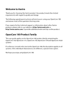 2
2 -
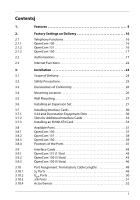 3
3 -
 4
4 -
 5
5 -
 6
6 -
 7
7 -
8
-
9
-
10
-
11
-
12
-
13
-
14
-
15
-
16
-
17
-
18
-
19
-
20
-
21
-
22
-
23
-
24
-
25
-
26
-
27
-
28
-
29
-
30
-
31
-
32
-
33
-
34
-
35
-
36
-
37
-
38
-
39
-
40
-
41
-
42
-
43
-
44
-
45
-
46
-
47
-
48
-
49
-
50
-
51
-
52
-
53
-
54
-
55
-
56
-
57
-
58
-
59
-
60
-
61
-
62
-
63
-
64
-
65
-
66
-
67
-
68
-
69
-
70
-
71
-
72
-
73
-
74
-
75
-
76
-
77
-
78
-
79
-
80
-
81
-
82
-
83
-
84
-
85
-
86
-
87
-
88
-
89
-
90
-
91
-
92
-
93
-
94
-
95
-
96
-
97
-
98
-
99
-
100
-
101
-
102
-
103
-
104
-
105
-
106
-
107
-
108
-
109
-
110
-
111
-
112
-
113
-
114
-
115
-
116
-
117
-
118
-
119
-
120
-
121
-
122
-
123
-
124
-
125
-
126
-
127
-
128
-
129
-
130
-
131
-
132
-
133
-
134
-
135
-
136
-
137
-
138
-
139
-
140
-
141
-
142
-
143
-
144
-
145
-
146
-
147
-
148
-
149
-
150
-
151
-
152
-
153
-
154
-
155
-
156
-
157
-
158
-
159
-
160
-
161
-
162
-
163
-
164
-
165
-
166
-
167
-
168
-
169
-
170
-
171
-
172
-
173
-
174
-
175
-
176
-
177
-
178
-
179
-
180
-
181
-
182
-
183
-
184
-
185
-
186
-
187
-
188
-
189
-
190
-
191
-
192
-
193
-
194
-
195
-
196
-
197
-
198
-
199
-
200
-
201
-
202
-
203
-
204
-
205
-
206
-
207
-
208
-
209
-
210
-
211
-
212
-
213
-
214
-
215
-
216
-
217
-
218
-
219
-
220
-
221
-
222
-
223
-
224
-
225
-
226
-
227
-
228
-
229
-
230
-
231
-
232
-
233
-
234
-
235
-
236
-
237
-
238
-
239
-
240
-
241
-
242
-
243
-
244
 |
 |

130
OpenCom 100
131
150
Mounting and Commissioning
User Guide