Aastra OpenCom 130 User Guide - Page 31
Please note, nection to a corporate LAN. You can connect an existing Ethernet connection
 |
View all Aastra OpenCom 130 manuals
Add to My Manuals
Save this manual to your list of manuals |
Page 31 highlights
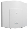
Installation Installing an Expansion Set expansion module using the Phillips screws provided in the expansion set (see "1" to "4" in the diagram). 2. 1. A Installing the power supply for the expansion module 5. Place the power supply to the right of the expansion module. Carefully press the power supply into the mounting recess provided (shown in the diagram as "1"). Move the power supply forwards until it snaps into place in all six pressure terminals ("A", "2"). 6. Connect the power supply output (flat conductor cable) to the appropriate jack of the expansion module. Insert the fully insulated connector of the mains supply in the power supply connection provided. 7. Establish an Ethernet connection between the LAN port of the basic module and the LAN1 port of the expansion module (see also Positions of the Ports starting on page 41). To do this, use the short Ethernet connection cable from the expansion set. The LAN0 port of the expansion module is intended for connection to a corporate LAN. You can connect an existing Ethernet connection cable to the LAN0 port of the expansion module. You usually install at least one interface card on the expansion module. To do this, read the instructions in the following section. Please note: Two power supplies are provided for the OpenCom 130 with an expansion module. Always turn on the power supply of 29
-
 1
1 -
2
-
3
-
4
-
5
-
6
-
7
-
8
-
9
-
10
-
11
-
12
-
13
-
14
-
15
-
16
-
17
-
18
-
19
-
20
-
21
-
22
-
23
-
24
-
25
-
 26
26 -
 27
27 -
 28
28 -
 29
29 -
 30
30 -
 31
31 -
 32
32 -
 33
33 -
 34
34 -
 35
35 -
 36
36 -
37
-
38
-
39
-
40
-
41
-
42
-
43
-
44
-
45
-
46
-
47
-
48
-
49
-
50
-
51
-
52
-
53
-
54
-
55
-
56
-
57
-
58
-
59
-
60
-
61
-
62
-
63
-
64
-
65
-
66
-
67
-
68
-
69
-
70
-
71
-
72
-
73
-
74
-
75
-
76
-
77
-
78
-
79
-
80
-
81
-
82
-
83
-
84
-
85
-
86
-
87
-
88
-
89
-
90
-
91
-
92
-
93
-
94
-
95
-
96
-
97
-
98
-
99
-
100
-
101
-
102
-
103
-
104
-
105
-
106
-
107
-
108
-
109
-
110
-
111
-
112
-
113
-
114
-
115
-
116
-
117
-
118
-
119
-
120
-
121
-
122
-
123
-
124
-
125
-
126
-
127
-
128
-
129
-
130
-
131
-
132
-
133
-
134
-
135
-
136
-
137
-
138
-
139
-
140
-
141
-
142
-
143
-
144
-
145
-
146
-
147
-
148
-
149
-
150
-
151
-
152
-
153
-
154
-
155
-
156
-
157
-
158
-
159
-
160
-
161
-
162
-
163
-
164
-
165
-
166
-
167
-
168
-
169
-
170
-
171
-
172
-
173
-
174
-
175
-
176
-
177
-
178
-
179
-
180
-
181
-
182
-
183
-
184
-
185
-
186
-
187
-
188
-
189
-
190
-
191
-
192
-
193
-
194
-
195
-
196
-
197
-
198
-
199
-
200
-
201
-
202
-
203
-
204
-
205
-
206
-
207
-
208
-
209
-
210
-
211
-
212
-
213
-
214
-
215
-
216
-
217
-
218
-
219
-
220
-
221
-
222
-
223
-
224
-
225
-
226
-
227
-
228
-
229
-
230
-
231
-
232
-
233
-
234
-
235
-
236
-
237
-
238
-
239
-
240
-
241
-
242
-
243
-
244
 |
 |
