Aastra OpenCom 130 User Guide - Page 34
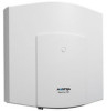
Slots for Additional Interface Cards, CAUTION, Telephony: Ports: Slots, Status
 |
View all Aastra OpenCom 130 manuals
Add to My Manuals
Save this manual to your list of manuals |
Page 34 highlights
Installation Installing Interface Cards CAUTION! Static charges can damage electronic components. Pay attention to the regulations regarding the handling of electrostatically sensitive components. 3. Carefully insert the interface card in the slot provided. The component side must face to the right. Ensure the plug-in connection is sitting securely. 4. Connect the required port cable to the corresponding pressure terminals or RJ45 jacks (see also Positions of the Ports starting on page 41). 5. Close the housing cover. Turn on the OpenCom 100. You can query the status of the doorstation equipment interface card and the V.24 interface card in the Web console when the OpenCom 100 is operational again. To do this, call up the Telephony: Ports: Slots menu page. The Status column in the table displays a green tick beside the name of the interface card. 3.7.2 Slots for Additional Interface Cards The OpenCom 131 offers one large slot to operate an additional interface card. The interface card is connected with two port jacks. The OpenCom 130 has three (the OpenCom 150 five) large slots in which you can operate interface cards. Each interface card is connected to the expansion module resp. to the main module via two port jacks. The following properties characterise the large slots of the OpenCom 130 / 150: ■ There is no prescribed order in which to use the jacks. You can, for example, therefore operate an interface card in slot 3 even though slot 2 is not occupied. ■ Each of the slots is connected to a group of pressure terminals. Therefore there are also three pressure terminal groups on the expansion module of the OpenCom 130 (five on the main module of an OpenCom 150). To be able to distinguish these, all the pressure terminals in a group are the same colour. 32
-
 1
1 -
2
-
3
-
4
-
5
-
6
-
7
-
8
-
9
-
10
-
11
-
12
-
13
-
14
-
15
-
16
-
17
-
18
-
19
-
20
-
21
-
22
-
23
-
24
-
25
-
26
-
27
-
28
-
 29
29 -
 30
30 -
 31
31 -
 32
32 -
 33
33 -
 34
34 -
 35
35 -
 36
36 -
 37
37 -
 38
38 -
 39
39 -
40
-
41
-
42
-
43
-
44
-
45
-
46
-
47
-
48
-
49
-
50
-
51
-
52
-
53
-
54
-
55
-
56
-
57
-
58
-
59
-
60
-
61
-
62
-
63
-
64
-
65
-
66
-
67
-
68
-
69
-
70
-
71
-
72
-
73
-
74
-
75
-
76
-
77
-
78
-
79
-
80
-
81
-
82
-
83
-
84
-
85
-
86
-
87
-
88
-
89
-
90
-
91
-
92
-
93
-
94
-
95
-
96
-
97
-
98
-
99
-
100
-
101
-
102
-
103
-
104
-
105
-
106
-
107
-
108
-
109
-
110
-
111
-
112
-
113
-
114
-
115
-
116
-
117
-
118
-
119
-
120
-
121
-
122
-
123
-
124
-
125
-
126
-
127
-
128
-
129
-
130
-
131
-
132
-
133
-
134
-
135
-
136
-
137
-
138
-
139
-
140
-
141
-
142
-
143
-
144
-
145
-
146
-
147
-
148
-
149
-
150
-
151
-
152
-
153
-
154
-
155
-
156
-
157
-
158
-
159
-
160
-
161
-
162
-
163
-
164
-
165
-
166
-
167
-
168
-
169
-
170
-
171
-
172
-
173
-
174
-
175
-
176
-
177
-
178
-
179
-
180
-
181
-
182
-
183
-
184
-
185
-
186
-
187
-
188
-
189
-
190
-
191
-
192
-
193
-
194
-
195
-
196
-
197
-
198
-
199
-
200
-
201
-
202
-
203
-
204
-
205
-
206
-
207
-
208
-
209
-
210
-
211
-
212
-
213
-
214
-
215
-
216
-
217
-
218
-
219
-
220
-
221
-
222
-
223
-
224
-
225
-
226
-
227
-
228
-
229
-
230
-
231
-
232
-
233
-
234
-
235
-
236
-
237
-
238
-
239
-
240
-
241
-
242
-
243
-
244
 |
 |
